Content
-
IPv4 Addressing - This section provides a review of IPv4 addressing and covers issues you might face and how to troubleshoot them.
-
DHCP for IPv4 - This section reviews DHCP for IPv4 operations, explores potential DHCP issues, and examines the output of various DHCP show commands.
-
IPv6 Addressing - This section provides a brief review of IPv6 addressing.
-
IPv6 SLAAC, Stateful DHCPv6, and Stateless DHCPv6 - This section explores how clients obtain IPv6 addressing information using SLACC, stateful DHCPv6, and stateless DHCPv6.
-
Packet-Forwarding Process - This section discusses the packet-forwarding process and the commands to verify the entries in the data structures that are used for this process. It also provides you with a collection of Cisco IOS commands that are useful when troubleshooting.
-
Routing Information Sources - This section explains which sources of routing information are the most believable and how the routing table interacts with various data structures to populate itself with the best information.
-
Static Routes - This section reviews how to configure and verify IPv4 and IPv6 static routes.
-
Trouble Tickets - This section provides a number of trouble tickets that demonstrate how a structured troubleshooting process is used to solve a reported problem.
IPv4 Addressing
-
Just as your personal street address uniquely defines where you live, an IPv4 address uniquely defines where a device resides in a network.
-
If devices are addressed incorrectly, they may not receive the packets that are intended for them.
-
It is imperative that you have a solid understanding of IPv4 addressing and how to verify that devices are addressed correctly on a network.
-
This section provides a review of IPv4 addressing and discusses issues you might face and how to troubleshoot them.
IPv4 Addressing Issues
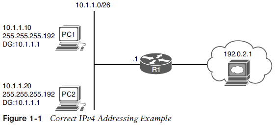
An IPv4 address is made up of two parts: a network/subnet portion and a host portion. It is imperative that all devices in the same network/subnet share exactly the same network/subnet portion.
When PC1 needs to communicate with PC2, it does a DNS lookup for the IP address of PC2. The IP address 10.1.1.20 is returned.
Now PC1 needs to determine whether PC2 is located in the same subnet because this determines whether the frame has the MAC address of PC2 or the MAC address of the default gateway (DG). PC1 determines its network/subnet portion by comparing its IP address to its subnet mask in binary, as follows:
00001010.00000001.00000001.00001010 - PC1 IP addr 11111111.11111111.11111111.11000000 - PC1 subnet mask
00001010.00000001.00000001.00 - PC1 network/subnet ID
Now PC1 compares exactly the same binary bits to those binary bits in PC2’s address, as follows:
00001010.00000001.00000001.00 - PC1 network/subnet ID 00001010.00000001.00000001.00010100 - PC2 IP address in binary
Because the binary bits are the same, PC1 concludes that PC2 is in the same network/subnet. Therefore, it communicates directly with it and does not need to send the data to its default gateway. PC1 creates a frame with its own source MAC address and the MAC address of PC2 as the destination.
Consider what occurs when PC1 needs to communicate with a web server at 192.0.2.1. Now PC1 needs to determine whether the web server is located in the same network/subnet. This determines whether the frame has the MAC address of the web server or the MAC address of the DG.
PC1 determines its network/subnet portion by comparing its IP address to its subnet mask in binary:
00001010.00000001.00000001.00001010 - PC1 IP address in binary
11111111.11111111.11111111.11000000 - PC1 subnet mask in binary
00001010.00000001.00000001.00 - PC1 network/subnet ID
Now PC1 compares the same binary bits to those binary bits in the web server address:
00001010.00000001.00000001.00 - PC1 network/subnet ID
11000000.00000000.00000010.00000001 - web server IP address
The web server is in a different network/subnet because the bits are not the same; therefore, to communicate with the web server, it needs to send the data to its default gateway. PC1 creates a frame with its own source MAC address and the MAC address of R1 as the destination.
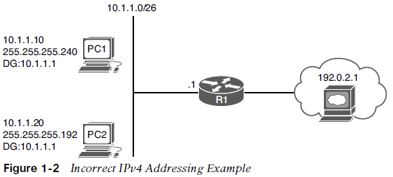
The following happens if PC1 is configured with the wrong subnet mask (255.255.255.240), as shown in Fig 1-2.
PC1 determines its network/subnet portion by comparing its IP address to its subnet mask in binary:
00001010.00000001.00000001.00001010 - PC1 IP address in binary
11111111.11111111.11111111.11110000 - PC1 subnet mask in binary
00001010.00000001.00000001.0000 - PC1 network/subnet ID
Now PC1 compares exactly the same binary bits to those binary bits in PC2’s address:
00001010.00000001.00000001.0000 - PC1 network/subnet ID
00001010.00000001.00000001.00010100 - PC2 IP address in binary
PC1 concludes that PC2 is not in the same network/subnet because the binary bits are not the same. Therefore, it needs to send the frame to the router so that the router can route the packet to the subnet PC2 is in. However, the PCs are actually connected to the same subnet, and as a result, there is an IPv4 addressing and connectivity issue.
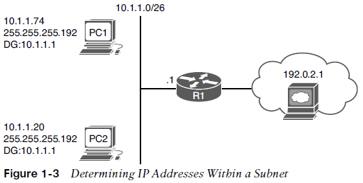
Determining IP Addresses within a Subnet
How do you determine if all the IP addresses are in a particular subnet?
In the subnet mask, find the most interesting octet. In binary, it’s the octet with the last binary 1. In decimal, it’s the last octet that is greater than 0.
In this case, for 255.255.255.192, the fourth octet is the last octet with a value great than 0. The value of this octet is 192. Now, subtract 192 from 256. The result is 64. The number 64 represents the block size or the number you are counting by in that octet. The subnet in this case is 10.1.1.0/26, and because the block size is 64, this subnet begins at 10.1.1.0/26 and ends at 10.1.1.63/26. The next subnet is 10.1.1.64/26 to 10.1.1.127/26. The third subnet is 10.1.1.128/26 to 10.1.1.191/26, and so on.
PC1, PC2, and an interface on R1 are supposed to be in the same subnet/network block.
In this case PC1 falls in the range 10.1.1.64/26 to 10.1.1.127/26, whereas PC2 and the default gateway fall in the range 10.1.1.0/26 to 10.1.1.63/26. PC1 is in a different network/subnet. You must fix the address on PC1 so that it is within the correct network/subnet.
DHCP for IPv4
-
Dynamic Host Configuration Protocol (DHCP) is commonly used for assigning IPv4 address information to a network host.
-
DHCP allows a DHCP client to obtain an IP address, subnet mask, default gateway IP address, DNS server IP address, and other types of IP addressing information from a DHCP server.
DHCP DORA Process
Figure 1-4 illustrates the exchange of messages (Discover, Offer, Request, Acknowledgment [DORA] process) that occurs as a DHCP client obtains IP addressing information from a DHCP server.
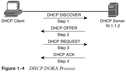
Step 1. When a DHCP client initially boots, it has no IP address, default gateway, or other configuration information. Therefore, the way a DHCP client initially communicates is by sending a broadcast DHCPDISCOVER message to destination IP 255.255.255.255 and destination MAC FFFF:FFFF:FFFF attempting to discover a DHCP server. The source IP is 0.0.0.0, and the source MAC is the MAC address of the sending device.
Step 2. When a DHCP server receives a DHCPDISCOVER message, it can respond with a DHCPOFFER message with an unleased IP address, subnet mask, and default gateway information. Because the DHCPDISCOVER message is sent as a broadcast, more than one DHCP server might respond with a DHCPOFFER. The client typically selects the server that sent the first DHCPOFFER response it received.
Step 3. The DHCP client communicates with the selected server by sending a broadcasted DHCPREQUEST message indicating that it will be using the address provided in the DHCPOFFER and, as a result, wants the associated address leased to itself.
Step 4. Finally, the DHCP server responds to the client with a DHCPACK message indicating that the IP address is leased to the client and includes any additional DHCP options that might be needed at this point, such as the lease duration.
DHCP Relay Agent
The DHCPDISCOVER message is sent as a broadcast but it cannot cross the router boundary. Therefore, if a client resides on a different network from the DHCP server, you need to configure the default gateway of the client as a DHCP relay agent to forward the broadcast packets as unicast packets to the server.
You use the ip helper-address ip_address interface configuration mode command to configure a router to relay DHCP messages to a DHCP server in the organization.
In the figure, the DHCP client belongs to the 172.16.1.0/24 network, whereas the DHCP server belongs to the 10.1.1.0/24 network. Router R1 is configured as a DHCP relay agent, using the syntax shown in Example 1-3.
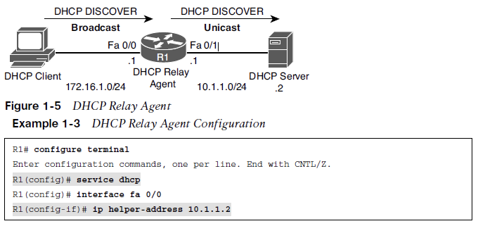
The service dhcp command enables the DHCP service on the router. It is usually not required because the DHCP service is enabled by default
The ip helper-address 10.1.1.2 command specifies the IP address of the DHCP server. If the wrong IP address is specified, the DHCP messages are relayed to the wrong device. In addition, the ip helper-address command must be configured on the interface that is receiving the DHCPDISCOVER messages from the clients.
As a DHCP relay agent, the router relays a few other broadcast types in addition to a DHCP message. Other protocols that are forwarded by a DHCP relay agent include the following:
- TFTP
- Domain Name System (DNS)
- Internet Time Service (ITS)
- NetBIOS name server
- NetBIOS datagram server
- BootP
- TACACS
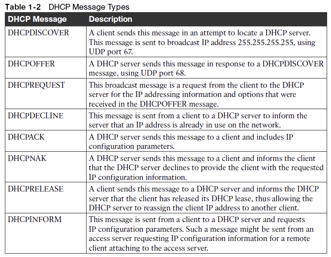
DHCP Message Types
Router as a DHCP client or a DHCP server
Router configured as a DHCP client so the router can obtain its IP address from a DHCP server:
R1# configure terminal
R1(config)# int fa 0/1
R1(config-if)# ip address dhcp
Router configured as a DHCP server:
R1(config)# ip dhcp excluded-address 10.8.8.1 10.8.8.10
R1(config)# ip dhcp pool POOL-A
R1(dhcp-config)# network 10.8.8.0 255.255.255.0
R1(dhcp-config)# default-router 10.8.8.1
R1(dhcp-config)# dns-server 192.168.1.1
R1(dhcp-config)# netbios-name-server 192.168.1.2
You do not have to include the IP address of the router interface in the excluded-address because the router never hands out its own interface IP address.
DHCP Troubleshooting Issues
Consider the following potential issues:
-
A router not forwarding broadcasts - A router needs to be explicitly configured to act as a DHCP relay agent if the DHCP client and DHCP server are on different subnets.
-
DHCP pool out of IP addresses - Once a pool becomes depleted, new DHCP requests are rejected.
-
Misconfiguration - The configuration of a DHCP server might be incorrect.
-
Duplicate IP addresses - Handing out an IP address to a client that is statically assigned to another host.
-
Redundant services not communicating - DHCP servers can coexist with other DHCP servers for redundancy. If inter-server communication fails, the DHCP servers hand out overlapping IP addresses to their client’s.
-
The “pull” nature of DHCP - The DHCP server has no ability to initiate a change in the client IP address after the client obtains an IP address. The DHCP server cannot push information changes to the DHCP client.
-
Interface not configured with IP address in DHCP pool - A router or a multilayer switch that is acting as a DHCP server must have an interface with an IP address that is part of the pool/subnet that it is handing out IP addresses for. This is not the case if a relay agent is forwarding DHCP messages between the client and the router that is the DHCP server.
DHCP Troubleshooting Commands
The show ip dhcp conflict command:
R1# show ip dhcp conflict
IP address Detection method Detection time
172.16.1.3 Ping Oct 15 2018 8:56 PM
The output indicates a duplicate 172.16.1.3 IP address on the network, which the router discovered via a ping. You clear the information displayed by issuing the clear ip dhcp conflict command * after resolving the duplicate address issue on the network.
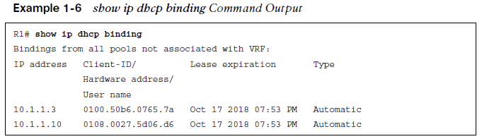
Example 1-6 shows the show ip dhcp binding command. The output indicates that IP address 10.1.1.10 was assigned to a DHCP client. You can release this DHCP lease with the clear ip dhcp binding 10.1.1.10 command.
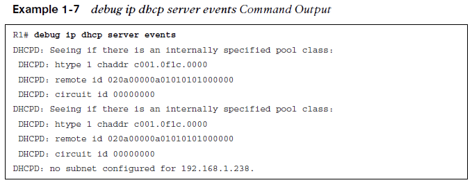
Example 1-7 shows sample output from the debug ip dhcp server events command. The output shows updates to the DHCP database.
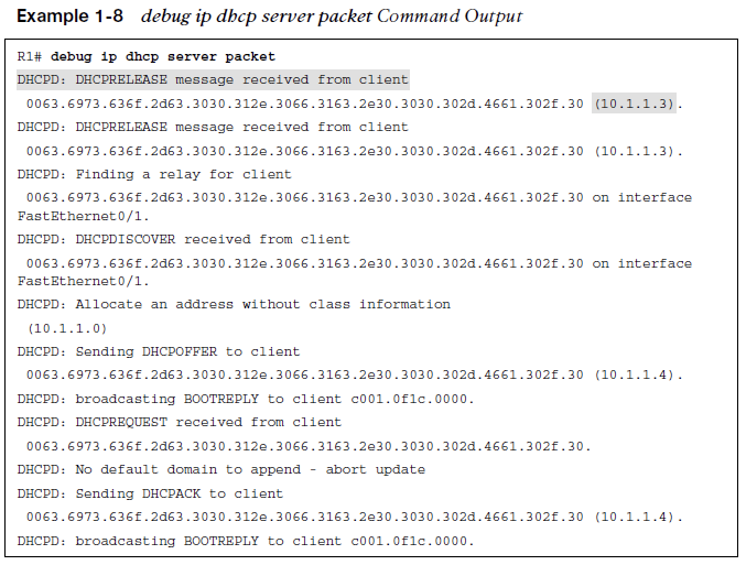
Example 1-8 shows sample output from the debug ip dhcp server packet command. The output shows a DHCPRELEASE message being received when a DHCP client with IP address 10.1.1.3 is shut down.
You can also see the four-step process of a DHCP client obtaining IP address 10.1.1.4 with the following messages:
DHCPDISCOVER, DHCPOFFER, DHCPREQUEST, DHCPACK
IPv6 Addressing
-
Just as your personal street address uniquely defines where you live, an IPv6 address uniquely defines where a device resides.
-
This section covers IPv6 addressing and assignment so that you are armed with the knowledge needed for troubleshooting IPv6 addressing issues.
IPv6 Addressing Review
Refer to Figure 1-8, which depicts an IPv6 network. 2001:db8:a:a::/64 represents the first 64 bits of the IPv6 address, which is the subnet prefix. This is the IPv6 network the nodes reside in. Router R1 has interface IPv6 address 2001:db8:a:a::1, where the last 64 bits, which are ::1 in this case, represent the interface/host ID or who it is in the IPv6 network.
PC1 is ::10, and PC2 is ::20. All the devices in 2001:db8:a:a::/64 are configured with the default gateway address of R1’s Gig0/0 interface, which is 2001:db8:a:a::1.
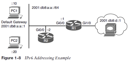
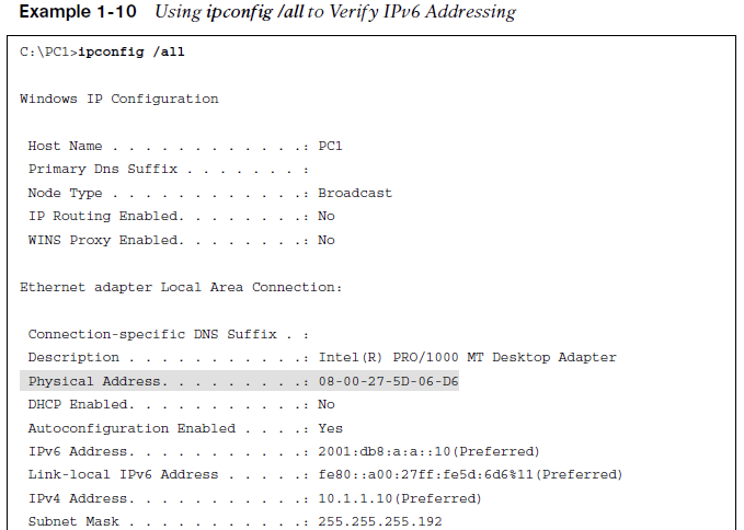
In this example, PC1 has the link-local address fe80::a00:27ff:fe5d:6d6 and the global unicast address 2001:db8:a:a::10, which was statically configured.
Notice the %11 at the end of the link-local address. This is the interface identification number, and it is needed so that the system knows which interface to send the packets out of; keep in mind that you can have multiple interfaces on the same device with the same link-local address assigned to it.

EUI-64
End devices can automatically assign their own IPv6 interface ID for global unicast and link local addresses, randomly or based on the IEEE EUI-64 standard.
EUI-64 takes the client’s MAC address, splits it in half, and adds the hex FFFE in the middle. In addition, it takes the seventh bit from the left and flips it. So, if it is a 1, it becomes a 0, and if it is a 0, it becomes a 1.
Example 1-10 Notice that the MAC address is 08 00 27 5D 06 D6. Split it in half and add FFFE in the middle to get 08 00 27 FF FE 5D 06 D6 or 0800:27FF:FE5D:06D6. This is close to what is listed in the link local address, but is not exactly the same. The interface ID in the link local address starts with 0a, and ours starts with 08. This is because the seventh bit is flipped. Flip it. 08 hex in binary is 00001000. The seventh bit from left to right is a 0, so make it a 1. Now you have 00001010. Convert to hex, and you get 0a. So, your interface ID is 0A00:27FF:FE5D:06D6.
Modern Windows PCs randomly generate the interface portion by default for both the link-local address and the global unicast address when autoconfiguring their IPv6 addresses. However, this can be changed so that EUI-64 is used instead.
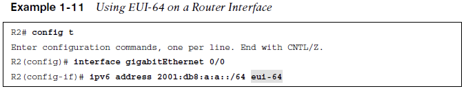
On a router, if you want to use EUI-64 for a statically configured global unicast address, use the_eui-64 keyword_ at the end of the ipv6 address command.
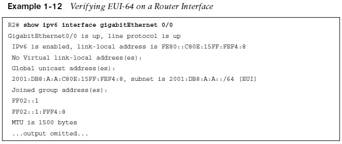
Verify the global unicast address and the EUI-64 interface ID assigned to an interface by using the show ipv6 interface command.
IPv6 SLAAC, Stateful DHCPv6, and Stateless DHCPv6
-
Manually assigning IP addresses (either IPv4 or IPv6) is not a scalable option.
-
With IPv4, DHCP provides a dynamic addressing option. With IPv6, you have three dynamic options to choose from: stateless address autoconfiguration (SLAAC), stateful DHCPv6, or stateless DHCPv6.
-
This section looks at the issues that might arise for each and how to troubleshoot them.
SLAAC
SLAAC is designed to enable a device to configure its own IPv6 address, prefix, and default gateway without a DHCPv6 server. Windows PCs automatically have SLAAC enabled and generate their own IPv6 addresses.
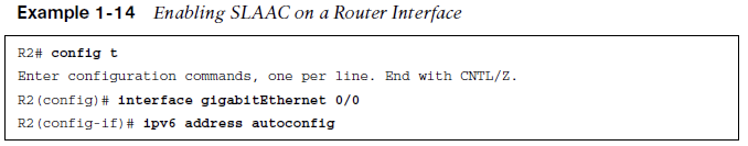
On Cisco routers, if you want to take advantage of SLAAC, you need to enable it manually on an interface with the ipv6 address autoconfig command.
When a PC and router interface are enabled for SLAAC, they send a Router Solicitation (RS) message to determine whether there are any routers connected to the local link.
They wait for a router to send a Router Advertisement (RA) that identifies the prefix being used by the router (the default gateway) connected to the same network.
They use that prefix information to generate their own IPv6 address in the same network as the router interface that generated the RA.
The router uses EUI-64 for the interface ID, and the PC randomly generates the interface ID unless it is configured to use EUI-64. In addition, the PC uses the IPv6 link-local address of the device that sent the RA as the default gateway address.
Figure 1-9 R1 sends an RA.
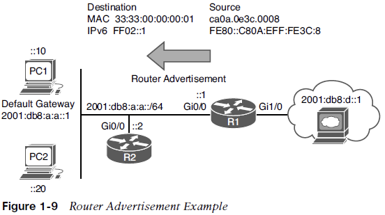
The source IPv6 address is the Gig0/0 link-local address, and the source MAC address is the MAC of Gig0/0. The destination IPv6 address is the all-nodes link-local multicast IPv6 address FF02::1. The destination MAC address is the all-nodes destination MAC address 33:33:00:00:00:01. By default, all IPv6-enabled interfaces listen for packets and frames destined for these two addresses.
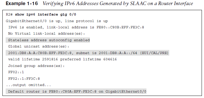
To verify an IPv6 address generated by SLAAC on a router interface, use the show ipv6 interface command.
As shown in Example 1-16, the global unicast address was generated using SLAAC. Also notice at the bottom of the example that the default router is listed as the link-local address of R1. However, note that this occurs only if IPv6 unicast routing was not enabled on router R1 and, as a result, the router is acting as an end device.
Router Adverrisements (RA)
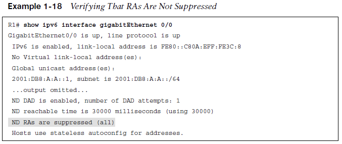
RAs are generated by default on router interfaces only if the router interface is enabled for IPv6, IPv6 unicast routing is enabled, and RAs are not being suppressed on the interface. Therefore, if SLAAC is not working, check the following:
-
ipv6 unicast-routing is configured.
-
The appropriate interface is enabled for IPv6 by using the show ipv6 interface command.
-
The router interface advertising RAs has a /64 prefix (SLAAC works only if the router is using a /64 prefix).
-
That RAs are not being suppressed on the interface, as shown in Example 1-18.
Stateful DHCPv6
With SLAAC a device can determine its IPv6 address, prefix, and default gateway but not much else.
In modern networks devices may need additional information such as NTP server, domain name, DNS server, and TFTP server. To hand out the IPv6 addressing information along with all optional information, use a Stateful DHCPv6 server. Both Cisco routers and multilayer switches may act as DHCP servers.
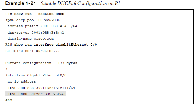
Example 1-21 provides a sample DHCPv6 configuration on R1 and the ipv6 dhcp server interface command necessary to enable the interface to use the DHCP pool for handing out IPv6 addressing information.
Although it is not pictured in Example 1-21 the ipv6 nd managed-config-flag interface configuration command on interface GigabitEthernet 0/0 ensures that the RA from router R1 informs the client to contact a DHCPv6 server for all IPv6 network addressing, prefix length, and other information.
Stateless DHCPv6
Stateless DHCPv6 is a combination of SLAAC and DHCPv6.
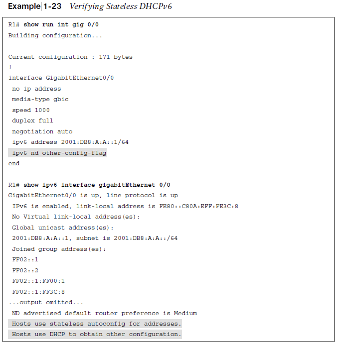
The router’s RA is used by the clients to automatically determine the IPv6 address, prefix, and default gateway. Also included in the RA is a flag that tells the client to get other non-addressing information from a DHCPv6 server, such as the address of a DNS server or a TFTP server. To accomplish this, ensure that the ipv6 nd other-config-flaginterface configuration command is enabled. This ensures that the RA informs the client that it must contact a DHCPv6 server for other information.
In Example 1-23, the output of show ipv6 interface gigabitEthernet 0/0states that hosts obtain IPv6 addressing from stateless autoconfig and other information from a DHCP server.
DHCPv6 Operation
DHCPv6 has a four-step negotiation process, like IPv4. However, DHCPv6 uses the following messages:
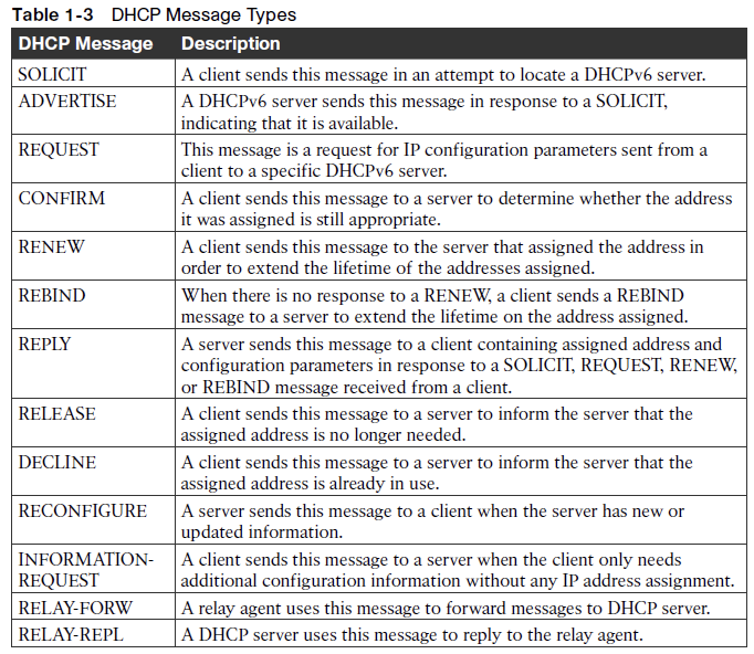
Step 1. SOLICIT - A client sends this message to locate DHCPv6 servers using the multicast address FF02::1:2, which is the all-DHCPv6-servers multicast address.
Step 2. ADVERTISE - Servers respond to SOLICIT messages with a unicast ADVERTISE message, offering addressing information to the client.
Step 3. REQUEST - The client sends this message to the server, confirming the addresses provided and any other parameters.
Step 4. REPLY - The server finalizes the process with this message.
DHCPv6 Messages
Table 1-3 provides a comprehensive list of DHCPv6 message types you might encounter while troubleshooting a DHCPv6 issue.
DHCPv6 Relay Agent
If you review the multicast address of the SOLICIT message, notice that it is a link-local scope multicast address. It starts with FF02. Therefore, the multicast does not leave the local network, and the client is not able to reach the DHCPv6 server.
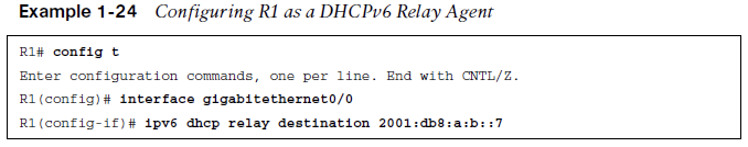
To relay the DHCPv6 messages to a DHCPv6 server in another network, the local router interface in the network the client belongs to needs to be configured as a relay agent with the ipv6 dhcp relay destination interface configuration command.
Example 1-24 shows interface Gigabit Ethernet 0/0 configured with the command ipv6 dhcp relay destination 2001:db8:a:b::7, which is used to forward SOLICIT messages to a DHCPv6 server at the address listed.
Packet-Forwarding Process
-
This section discusses the packet-forwarding process and the commands used to verify the entries in the data structures that are used for this process.
-
It also provides you with a collection of Cisco IOS software commands that are useful when troubleshooting related issues.
Reviewing the Layer 3 Packet-Forwarding Process
If you are experiencing connectivity issues between two hosts on a network, you could check Layer 3 by pinging between the hosts.
If the pings are successful, the issue resides at upper layers of the OSI reference model (Layers 4 through 7). If the pings fail, you should troubleshoot Layers 1 through 3.
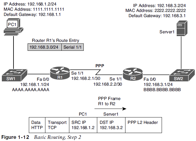
If you determine the problem is at Layer 3, you might look at the packet-forwarding process of a router. Review the Layer 3 Packet-Forwarding Process consider Figure 1-10. In this topology, PC1 needs to access HTTP resources on Server1. Notice that PC1 and Server1 are on different networks.
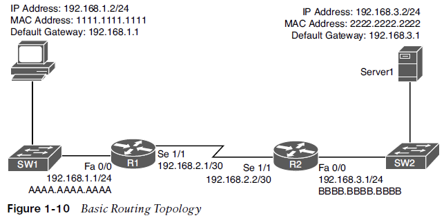
Step 1. PC1 concludes that the destination IP address resides on a remote subnet. Therefore, PC1 needs to send the frame to its default gateway.
PC1 has the default gateway address 192.168.1.1 which is router R1.
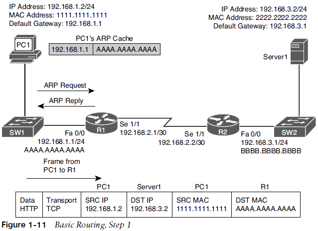
To construct a Layer 2 frame, PC1 needs the MAC address of the frame’s destination, which is PC1’s default gateway.
If the MAC address is not in PC1’s Address Resolution Protocol (ARP) cache, PC1 uses ARP to discover it. Once PC1 receives an ARP reply from router R1, PC1 adds router R1’s MAC address to its ARP cache. PC1 then sends its data destined for Server1 in a frame addressed to R1, as shown in Figure 1-11.
Step 2. R1 receives the frame sent from PC1, and because the destination MAC address is R1’s, R1 tears off the Layer 2 header and interrogates the Layer 3 header.
Router R1 decrements the packet’s TTL field. If the value in the TTL field is reduced to zero, the router discards the packet and sends a time-exceeded ICMP message back to the source.
Assuming the TTL is not decremented to zero, R1 checks its routing table to determine the best path to reach the IP address 192.168.3.2.
R1’s routing table has an entry stating that network 192.168.3.0/24 is accessible through interface Serial 1/1. ARP is not required for serial interfaces because they do not have MAC addresses. Therefore, R1 forwards the frame out its Serial 1/1 interface, using the Point-to-Point Protocol (PPP) Layer 2 framing header.
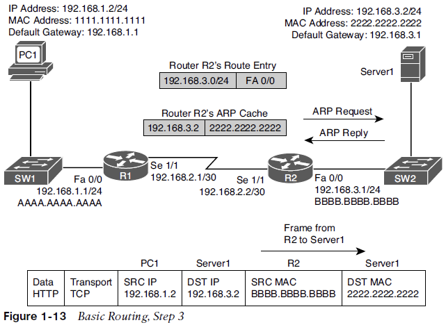
Step 3. When router R2 receives the frame, it removes the PPP header and then decrements the TTL in the IP header, just as router R1 did.
Again, assuming that the TTL did not get decremented to zero, router R2 interrogates the IP header to determine the destination network.
In this case, the destination network 192.168.3.0/24 is directly attached to router R2’s Fast Ethernet 0/0 interface.
R2 sends an ARP request to determine the MAC address of Server1 if it is not already known in the ARP cache.
Once an ARP reply is received from Server1, router R2 stores the results of the ARP reply in the ARP cache and forwards the frame out its Fast Ethernet 0/0 interface to Server1, as shown in Figure 1-13.
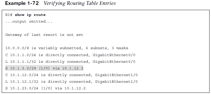
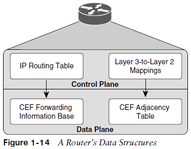
IP routing table - When a router needs to route an IP packet, it consults its IP routing table to find the best match. The best match is the route that has the longest prefix. For example, suppose a router has a routing entry for networks 10.0.0.0/8, 10.1.1.0/24, and 10.1.1.0/26. Also, suppose that the router is trying to forward a packet with the destination IP address 10.1.1.10. The router selects the 10.1.1.0/26 route entry as the best match because that route entry has the longest prefix, /26 (it matches the most bits).
Layer 3-to-Layer 2 mapping table - In Figure 1-13, R2’s ARP cache contains Layer 3-to-Layer 2 mapping information. The ARP cache has a mapping that says MAC address 2222.2222.2222 corresponds to IP address 192.168.3.2. An ARP cache is the Layer 3-to-Layer 2 mapping data structure used for Ethernet networks, but similar data structures are used for Multipoint Frame Relay networks and Dynamic Multipoint Virtual Private Network (DMVPN). For PPP or HDLC networks, there is only one other possible device connected to the other end of the link, so no mapping information is needed to determine the next-hop device.
Querying a router’s routing table and its ARP cache is less than efficient. Fortunately, Cisco Express Forwarding (CEF) gleans its information from the router’s IP routing table and ARP cache. Then, CEF’s data structures in hardware can be referenced when forwarding packets.
The two primary CEF data structures are as follows:
Forwarding Information Base (FIB) - The FIB contains Layer 3 information, similar to the information found in an IP routing table. In addition, an FIB contains information about multicast routes and directly connected hosts.
Adjacency table - When a router performs a route lookup using CEF, the FIB references an entry in the adjacency table. The adjacency table entry contains frame header information required by the router to properly form a frame. An egress interface and a next-hop MAC address is in an adjacency entry for a multipoint Ethernet interface, whereas a point-to-point interface requires only egress interface information.
Troubleshooting the Packet-Forwarding Process
When troubleshooting packet-forwarding issues, you need to examine a router’s IP routing table. If the observed behavior of the traffic is not conforming to information in the IP routing table, remember that the IP routing table is maintained by a router’s control plane and is used to build the tables at the data plane.
CEF is operating in the data plane and uses the FIB. You need to view the CEF data structures (that is, the FIB and the adjacency table) that contain all the information required to make packet-forwarding decisions.
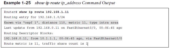
Example 1-25 provides sample output from the show ip route _ip_address_command. The output shows that the next-hop IP address to reach IP address 192.168.1.11 is 192.168.0.11, which is accessible via interface Fast Ethernet 0/0. Because this information is coming from the control plane, it includes information about the routing protocol OSPF.
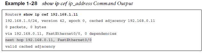
Example 1-28 provides sample output from the show ip cef _ip_address_command. The output indicates that, according to CEF, IP address 192.168.1.11 is accessible out interface FastEthernet 0/0, with the next-hop IP address 192.168.0.11.
The following snippet provides sample output from the show ip cef exact-route _source_address destination_address_command:
Router# show ip cef exact-route 10.2.2.2 192.168.1.11

10.2.2.2 -> 192.168.1.11 : FastEthernet0/0 (next hop 192.168.0.11)
The output indicates that a packet sourced from IP address 10.2.2.2 and destined for IP address 192.168.1.11 will be sent out interface FastEthernet 0/0 to next-hop IP address 192.168.0.11.
For a multipoint interface such as point-to-multipoint Frame Relay or Ethernet, when a router knows the next-hop address for a packet, it needs appropriate Layer 2 information (for example, next-hop MAC address or data link connection identifier [DLCI]) to properly construct a frame.
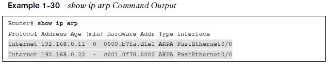
Example 1-30 provides sample output from the show ip arp command, which displays the ARP cache that is stored in the control plane on a router. The output shows the learned or configured MAC addresses along with their associated IP addresses.
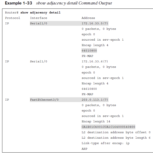
Example 1-33 provides sample output from the show adjacency detail command.
The output shows the CEF information used to construct frame headers needed to reach the next-hop IP addresses through the various router interfaces.
Notice the value 64510800 for Serial 1/0. This is a hexadecimal representation of information that is needed by the router to successfully forward the packet to the next-hop IP address 172.16.33.5, including the DLCI 405. Notice the value CA1B01C4001CCA1C164000540800 for Fast Ethernet 3/0. This is the destination MAC address, the source MAC address, and the EtherType code for an Ethernet frame. The first 12 hex values are the destination MAC address, the next 12 are the source MAC address, and 0800 is the IPv4 EtherType code.
Routing Information Sources
- This section explains which sources of routing information are the most believable and how the routing table interacts with various data structures to populate itself with the best information.
Data Structures and the Routing Table
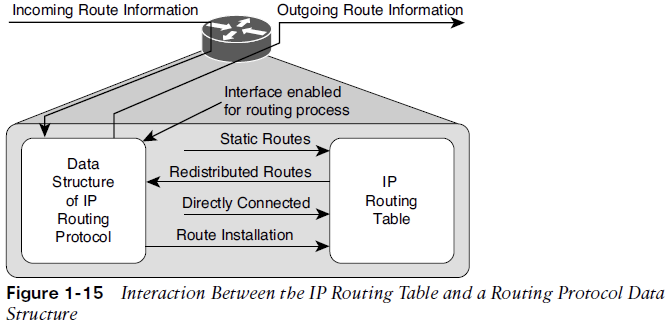
As a router receives routing information from a neighboring router, the information is stored in the data structures of the IP routing protocol and analyzed by the routing protocol to determine the best path, based on metrics.
An IP routing protocol’s data structure can also be populated by the local router. For example, a router might be configured for route redistribution, where routing information is redistributed from the routing table into the IP routing protocol’s data structure. Specific interfaces can also participate in the IP routing protocol process and the network that the interface belongs to is placed into the routing protocol data structure as well.
Review Figure 1-15, the routing protocol data structure can populate the routing table, a directly connected route and static routes can populate the routing table. These are all known as sources of routing information.
Sources of Routing Information
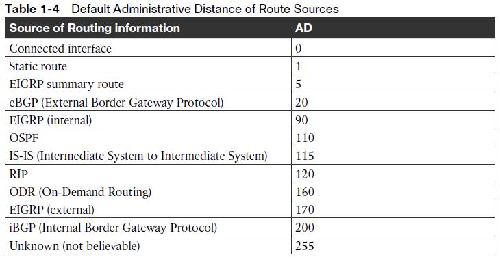
Routing information sources are each assigned an administrative distance (AD). Administrative distance is the believability or trustworthiness of a routing source when comparing it to the other routing information sources.
Table 1-4 lists the default ADs of routing information sources. The lower the AD, the more preferred the source.
Routes are injected into the routing table only if the router concludes that they came from the best routing source. If you ever need to make sure that the routing information or subset of routing information received from a particular source is never used, change the AD of specific routes or all routes from that source to 255, which means “do not believe.” Another option is to create a floating static route which is a backup route configured to have a higher AD and therefore be less preferred, than the route that is preferred.
Static Routes
- This section discusses the syntax of IPv4 and IPv6 static routes and explains what to look for while troubleshooting.
IPv4 Static Routes
Basic Configuration
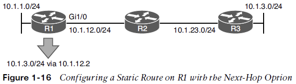
Static routes are manually configured by administrators. They are the second-most-trustworthy source of routing information, with an AD of 1. They allow an administrator to precisely control how to route packets for a particular destination. The following is a configuration of a static route on R1. The static route tells R1 how to reach the 10.1.3.0/24 network:
R1(config)# ip route 10.1.3.0 255.255.255.0 10.1.12.2 8
The network is reachable via the next-hop address 10.1.12.2, which is R2, and is assigned an AD of 8. (The default is 1.)
When troubleshooting IPv4 static routes, you need to be able to recognize why the static route may not be providing the results you want.
Common Mistakes
Are the network and mask accurate? If either of them is incorrect, your static route will not route the packets you are expecting it to route. The router might drop packets because it does not match the static route or any other route. It might end up forwarding packets using the default route, which may be pointing the wrong way. In addition, if the static route includes networks that it should not, you could be routing packets the wrong way.
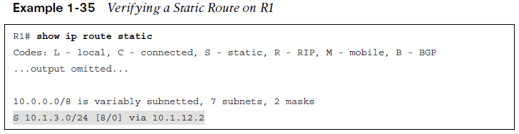
If you were to configure the static route ip route 10.1.3.0 255.255.255.0 10.1.12.1 on R2 in Figure 1-16, packets destined to 10.1.3.0 would be sent to R1, which is the wrong way. However, notice in Example 1-35 that R1 points to R2 (10.1.12.2) for the network 10.1.3.0/24. Therefore, R1 and R2 simply bounce packets that are destined for 10.1.3.0/24 back and forth until the TTL expires.
Recursive Lookup
Notice that the next-hop IP address is a very important parameter for the static route. It tells the local router where to send the packet.
For instance, in Example 1-35, the next hop is 10.1.12.2. Therefore, a packet destined to 10.1.3.0 has to go to 10.1.12.2 next. R1 now does a recursive lookup in the routing table for 10.1.12.2 to determine how to reach it, as shown in Example 1-36.
This example displays the output of the show ip route 10.1.12.2 command on R1. Notice that 10.1.12.2 is directly connected out GigabitEthernet 1/0.

Exit Interface
Imagine that users in the 10.1.1.0/24 network are trying to access resources on hosts 10.1.3.1 through 10.1.3.8. R1 receives the packets, and it looks in the routing table and finds that the longest match is the following entry:
S 10.1.3.0/24 is directly connected, GigabitEthernet1/0
R1 believes the network is directly connected; therefore, the destination IP address in the packet is on the network connected to Gig1/0. However, you know better because Figure 1-17 shows that it is not. So, because it is an Ethernet interface, R1 uses ARP to determine the MAC address of the IP address in the destination field of the packet. (This is different from what occurred when the next-hop IP address was specified. When the next hop was specified, the MAC address of the next-hop address was used.)
Proxy ARP
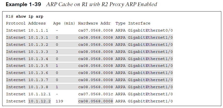
Example 1-39 shows the ARP cache on R1. Notice that every destination IP address has an entry in the ARP cache. How can that be if ARP requests are not forwarded by routers?
It is because of proxy ARP, which is on by default on the routers. Proxy ARP allows a router to respond to ARP requests with its own MAC address if it has a route in the routing table to the IP address in the ARP request. Notice that the MAC addresses listed are all the same. In addition, they match the MAC address of the 10.1.12.2 entry. Therefore, because R2 has a route to reach the IP address of the ARP request, it responds back with its MAC address.
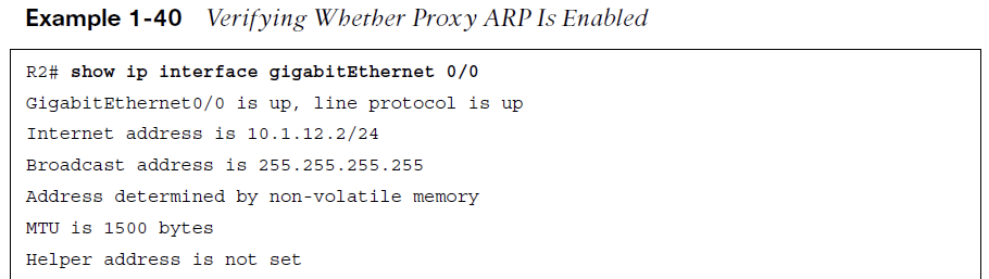
Example 1-40 shows how to use the show ip interface command to verify whether proxy ARP is enabled.
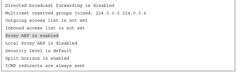
If proxy ARP is not enabled, the ARP cache on R1 appears as shown in Example 1-41. Notice that R1 is still sending ARP requests; however, it is not getting any ARP replies. Therefore, it cannot build the Layer 2 frame, and the result is an encapsulation failure.
Because of the fact that R1 uses ARP to determine the MAC address of every destination IP address in every packet, you should never specify an Ethernet interface in a static route. Specifying an Ethernet interface in a static route results in excessive use of router resources, such as processor and memory, as the control plane gets involved during the forwarding process to determine the appropriate Layer 2 MAC address using ARP.
Example 1-40 shows how to use the show ip interface command to verify whether proxy ARP is enabled.
If proxy ARP is not enabled, the ARP cache on R1 appears as shown in Example 1-41. Notice that R1 is still sending ARP requests; however, it is not getting any ARP replies. Therefore, it cannot build the Layer 2 frame, and the result is an encapsulation failure.
Because of the fact that R1 uses ARP to determine the MAC address of every destination IP address in every packet, you should never specify an Ethernet interface in a static route. Specifying an Ethernet interface in a static route results in excessive use of router resources, such as processor and memory, as the control plane gets involved during the forwarding process to determine the appropriate Layer 2 MAC address using ARP.
IPv6 Static Routes
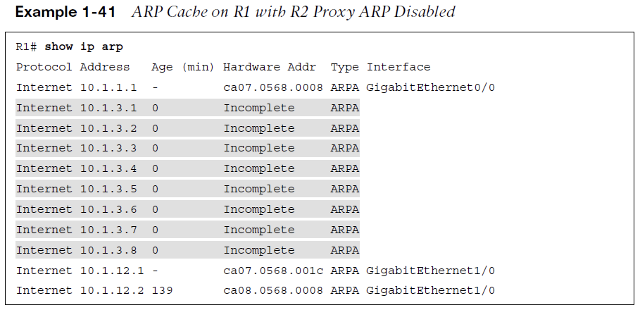
The following displays the configuration of an IPv6 static route on R1, as shown in Figure 1-18:
R1(config)# ipv6 route 2001:DB8:0:3::/64 gigabitEthernet 1/0 FE80::2 8
The static route tells R1 about the 2001:DB8:0:3::/64 network. The network is reachable using the next-hop address FE80::2, which is R2’s link-local address, and it was assigned an AD of 8. (The default is 1.)
Notice that the exit Ethernet interface is specified. This is mandatory when using the link-local address as the next hop because the same link-local address can be used on multiple local router interfaces. In addition, multiple remote router interfaces can have the same link-local address as well. As long as the link-local addresses are unique between the devices within the same local network, communication occurs as intended. If you are using a global unicast address as the next hop, you do not have to specify the exit interface.
There are no broadcasts with IPv6. Therefore, IPv6 does not use ARP. It uses NDP (Neighbor Discovery Protocol), which is multicast based, to determine a neighboring device’s MAC address.
In this case, if R1 needs to route packets to 2001:DB8:0:3::/64, the routing table says to use the next-hop address FE80::2, which is out Gig1/0. Therefore, it consults its IPv6 neighbor table, as shown in the following snippet, to determine whether there is a MAC address for FE80::2 out Gig 1/0:
R1# show ipv6 neighbors

IPv6 Address Age Link-layer Addr State Interface
FE80::2 0 ca08.0568.0008 REACH Gi1/0
If there is no entry in the IPv6 neighbor table, a neighbor solicitation message is sent to discover the MAC address FE80::2 on Gig1/0.
Proxy ARP does not exist in IPv6. Therefore, in an IPv6 static route if you only use the interface option with an Ethernet interface, it works only if the destination IPv6 address is directly attached to the router interface specified. This is because the destination IPv6 address in the packet is used as the next-hop address, and the MAC address needs to be discovered using NDP. If the destination is not in the directly connected network, neighbor discovery fails, and Layer 2 encapsulation ultimately fails.
ipv6 route 2001:DB8:0:3::/64 gigabitEthernet 1/0
When R1 receives a packet destined for 2001:db8:0:3::3, it determines based on the static route that it is directly connected to Gig1/0 (which it is not according to Figure 1-18). Therefore, R1 sends an Neighbor Solicitation (NS) out Gig1/0 for the MAC address associated with 2001:db8:0:3::3, using the solicited-node multicast address FF02::1:FF00:3. If no device attached to Gig1/0 is using the solicited-node multicast address FF02::1:FF00:3 and the IPv6 address 2001:db8:0:3::3, the NS goes unanswered, and Layer 2 encapsulation fails.
Trouble Tickets
-
This section presents various trouble tickets related to the topics discussed earlier.
-
The purpose of this section is to show you a process you can follow when troubleshooting in the real world or in an exam environment.
IPv4 Addressing and Addressing Technologies Trouble Tickets
- Trouble Ticket 1
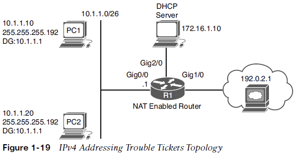
- Problem: PC1 is not able to access resources on web server 192.0.2.1.
-
A ping from PC1 to 192.0.2.1 fails
-
A ping from PC1 to the default gateway R1 at 10.1.1.1 succeeds
-
A ping from PC2 to 192.0.2.1 succeeds
-
Layer 2 & 3 connectivity from PC1 and PC2 to the router is fine
-
You have confirmed that PC2 can reach Internet resources
- Possible Reasons
-
An access control list (ACL) is denying PC1 from accessing resources on the Internet?
-
A NAT issue could be preventing 10.1.1.10 from being translated?
-
PC1 could be sending packets destined to a remote network to the wrong default gateway
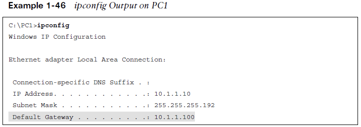
Answer - You see that the default gateway is configured as 10.1.1.100, which is not the IP address of R1’s interface.
Trouble Ticket 2
- Problem: PC1 is not able to access resources on web server 192.0.2.1.
-
A ping from PC1 to 192.0.2.1 fails
-
A ping from PC1 to the default gateway R1 at 10.1.1.1 fails
-
A ping from PC2 to 192.0.2.1 fails
-
A ping from PC2 to the default gateway R1 at 10.1.1.1 fails
-
No Layer 2 & 3 connectivity from PC1 and PC2 to the router
Possible Reasons
-
VLANs, VLAN ACLs, trunks, VTP, and STP are all possible?
-
Start with the simple solution and check IP addressing on PC1
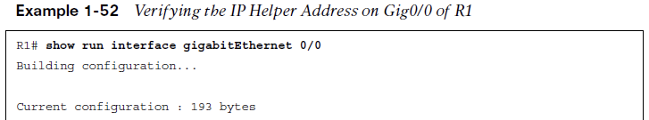
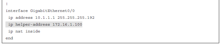
Answer - You see that PC1 has APIPA addressing and no default gateway, it cannot reach the DHCP server. The DHCP server is on another network which means the router needs to be configured to forward DHCP DISCOVER broadcasts. In Example 1-52. The output indicates that the IP helper address is 172.16.1.100, which is not correct according to the network diagram.
IPv6 Addressing Trouble Tickets
- Trouble Ticket 3
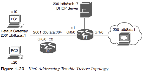
- Problem: PC1 is not able to access resources on web server 2001:db8:d::1.
-
A ping from PC1 to 2001:db8:d::1 fails
-
A ping from PC1 to the default gateway at 2001:db8:a:a::1 fails
-
An ipconfig reveals PC1 is not generating automatic addressing
-
An ipconfig reveals PC2 is not generating automatic addressing
Possible Reasons
-
Are the PCs configured for automatic addressing?
-
Is R1 configured to provide RAs to the PCs for SLAAC to work?
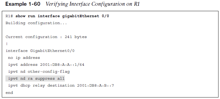
Answer - You issue the command show ipv6 interface gigabitEthernet 0/0 on R1. The output indicates that hosts use SLAAC for addresses, and DHCP is used for other configuration values. However, it also indicates that RAs are suppressed. You issue show run int g0/0 to verify the configuration on the interface. As shown Example 1-60, the interface is configured withipv6 nd ra suppress all, which stops R1 from sending RAs.
Static Routing Trouble Tickets
- Trouble Ticket 4
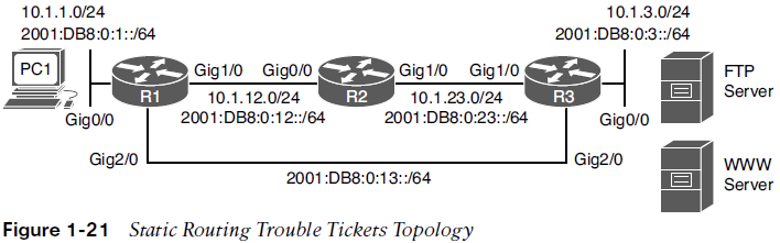
- Problem: Users in the 10.1.1.0/24 network are not able to access the FTP server at 10.1.3.10 nor the web server at 10.1.3.5.
-
A ping from PC1 to 10.1.3.10 fails
-
R1 responds with a _destination unreachable_message indicating there is not route
-
A ping from 10.1.3.5 to 10.1.3.10 is successful
- Possible Reasons
-
Does R1 have a route to the 10.1.3.0 network?
-
Do routers R2 and R3 have routes to the networks?
Answer – You issue the show ip route command on R1 to verify whether it knows how to route the packet to 10.1.3.10. The closest match in the routing table is a static route to the 10.1.3.0/29 network which means 10.1.3.10 is not covered by the range of addresses in the 10.1.3.0/29 subnet. You remove an replace the static route and pings are now successful.