Content
- Network Device Communication - This section explains how switches forward traffic from a Layer 2 perspective and routers forward traffic from a Layer 3 perspective.
- Forwarding Architectures - This section examines the mechanisms used in routers and switches to forward network traffic.
Network Device Communication
- The primary function of a network is to provide connectivity between devices.
- Today most everything is based on Transmission Control Protocol/Internet Protocol (TCP/IP).
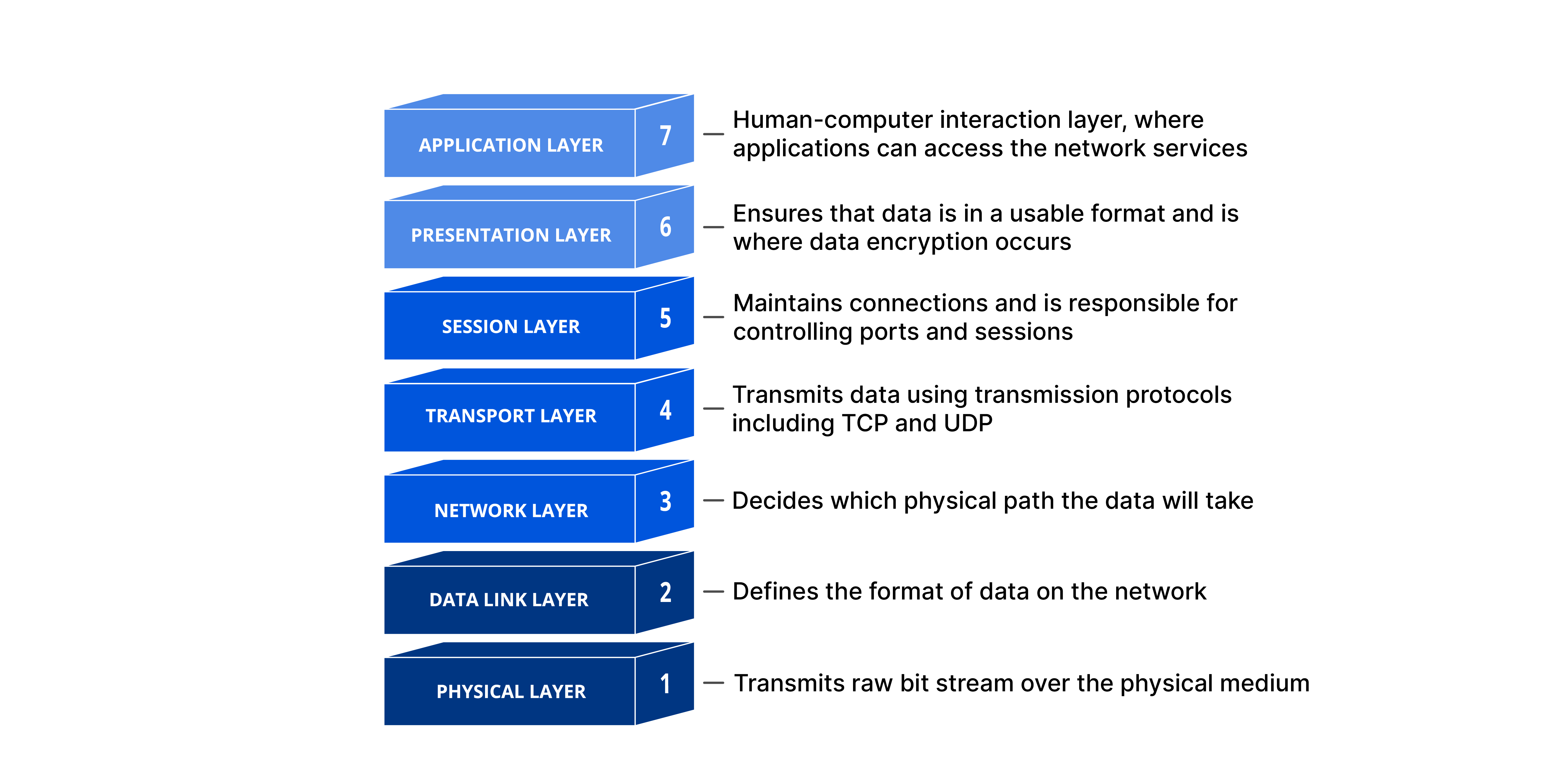
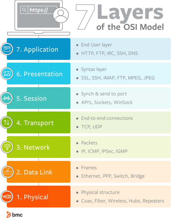
OSI Model
TCP/IP is based on the Open Systems Interconnection (OSI) model composed of seven layers, as shown in the figure.
Layer 2 Forwarding and Collision Domains
The data link layer handles addressing beneath the IP protocol stack so that communication is directed between hosts.
Ethernet commonly uses media access control addresses (MAC) and other data link layer protocols, such as Frame Relay, use an entirely different method of Layer 2 addressing. This course focused on MAC address for Layer 2 forwarding.
Collision Domains
- Ethernet devices use Carrier Sense Multiple Access/Collision Detection (CSMA/CD) to ensure that only one device talks at a time in a collision domain.
- Devices can only transmit or receive data at one time (operate a half-duplex).
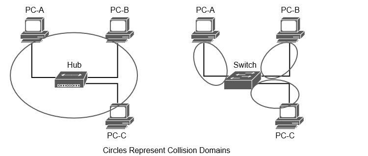
Collision Domains on a Hub Versus a Switch
-
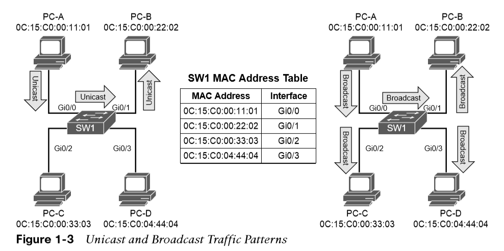
Unknown unicast flooding occurs when a packet contains a destination MAC address that is not in the switch’s MAC address table. The switch forwards the packet out of every switch port.
-
Broadcast traffic is network traffic intended for every host on the LAN and is forwarded out of every switch port interface.
-
Network broadcasts do not cross Layer 3 boundaries (from one subnet to another).
Virtual LANs
Adding a router between LAN segments helps shrink broadcast domains.
Virtual LANs (VLANS) provide logical segmentation by creating multiple broadcast domains on the same network switch. VLANs provide higher utilization of switch ports because a port can be associated to the necessary broadcast domain, and multiple broadcast domains can reside on the same switch.
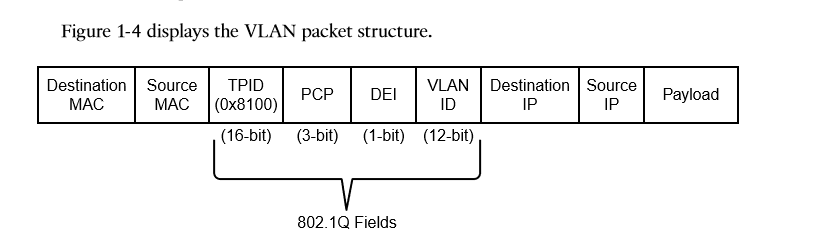
VLANS are defined in the IEEE 802.1Q standard, which sates that the 32 bits are added to the packet header with the following fields: Tag Protocol identifier (TPID), Priority Code Point (PCP), Drop Eligible Indicator (DEI), and VLAN Identifier (VLAN ID).
Creating a VLAN
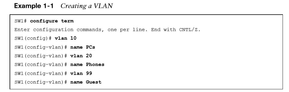
VLANs are created in the global configuration.
VLANs are named in the VLAN sub-global mode.
 VLANs and their port assignment are verified with the show vlan [{brief | id vlan-id | name vlanname | summary}] command.
The output is split into four main sections: VLAN-to-port assignments, system MTU, SPAN sessions, and private VLANs.
Optional show vlan keywords
Optional show vlan keywords provide the following benefits:
-
Brief - Displays only the relevant port-to-VLAN mappings.
-
Summary - Displays a count of VLANs, VLANs participating in VTP, and VLANs that in the extended VLAN range.
-
id vlan-id - Displays all the output from the original command but filtered to only the VLAN number that is specified.
-
name vlanname - Displays all the output from the original command but filtered to only the VLAN name that is specified.
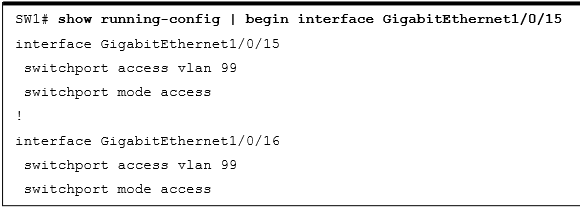
Access Ports
Access ports are the fundamental building blocks of a managed switch.
-
An access port is assigned to only one VLAN.
-
It carries traffic from the specified VLAN to the device connected to it or from the device to other devices on the same VLAN.
-
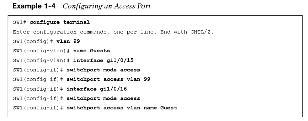
Catalyst switch ports are Layer 2 by default.
-
Use the command switchport mode access to manually configure a port as an access port.
-
A specific VLAN is associated to the port with the command switchport access {vlan vlan-id | name vlanname}.
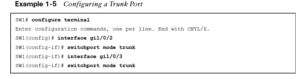
Trunk Ports
Trunk ports can carry multiple VLANs. They are typically used when multiple VLANs need connectivity between a switch and another switch, router, or firewall and use only one port. Trunk ports are statically defined on Catalyst switches with the interface command switchport mode trunk.
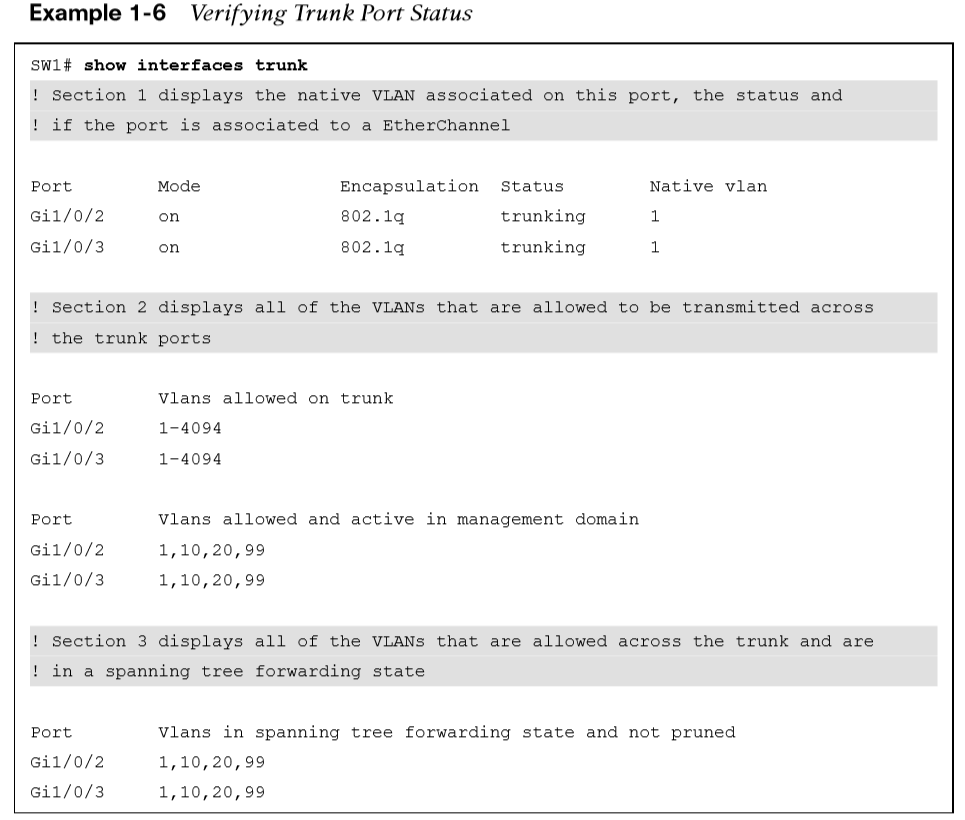
 The command show interfaces trunk provides a lot of valuable information:
-
The first section lists all the interfaces that are trunk ports, the status, the association to an EtherChannel, and whether a VLAN is a native VLAN.
-
The second section of the output displays the list of VLANs that are allowed on the trunk port. Traffic can be minimized on trunk ports to restrict VLANs to specific switches, thereby restricting broadcast traffic, too.
-
The third section displays the VLANs that are in a forwarding state on the switch. Ports that are in blocking state are not listed in this section.
Native VLANs
In the 802.1Q standard, any traffic that is advertised or received on a trunk port without the 802.1Q VLAN tag is associated to the native VLAN.
-
The default native VLAN is VLAN 1.
-
When a switch has two access ports configured as access ports and associated to VLAN 10—that is, a host attached to a trunk port with a native VLAN set to 10—the host could talk to the devices connected to the access ports.
-
The native VLAN should match on both trunk ports, or traffic can change VLANs unintentionally. While connectivity between hosts is feasible (assuming that they are on the different VLAN numbers), this causes confusion for most network engineers and is not a best practice.
-
A native VLAN is a port-specific configuration and is changed with the interface command switchport trunk native vlan vlan-id.
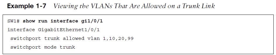
Allowed VLANs
The interface command switchport trunk allowed vlan vlan-ids_specifies the VLANs that are allowed to traverse the link. Example 1-7 displays sample a configuration for limiting the VLANs that can cross the Gi1/0/2 trunk port for VLANs 1, 10, 20, and 99.
•The full command syntax switchport trunk allowed {vlan-ids | all | none | add vlan-ids | remove vlan-ids | except vlan-ids} provides a lot of power in a single command.
•The optional keyword all allows for all VLANs, while noneremoves all VLANs from the trunk link.
•The add keyword adds additional VLANs to those already listed, and the remove keyword removes the specified VLAN from the VLANs already identified for that trunk link.
MAC Address Table
The MAC address table is responsible for identifying the switch ports and VLANs with which a device is associated. A switch builds the MAC address table by examining the source MAC address for the traffic that it receives. This information is then maintained to shrink the collision domain (point-to-point communication between devices and switches) by reducing the amount of unknown unicast flooding.
The MAC address table is displayed with the command show mac address-table [address mac-address | dynamic | vlan vlan-id]. The optional keywords with this command provide the following benefits:
-
address mac-address - Displays entries that match the explicit MAC address. This command could be beneficial on switches with hundreds of ports.
-
dynamic - Displays entries that are dynamically learned and are not statically set or burned in on the switch.
-
vlan vlan-id - Displays entries that matches the specified VLAN.
-
The command mac address-table static mac-address vlanvlan-id{drop | interface interface-id} adds a manual entry with the ability to associate it to a specific switch port or to drop traffic upon receipt.
-
The command clear mac address-table dynamic [{address mac-address| interface interface-id | vlan vlan-id}] flushes the MAC address table for the entire switch.
-
The MAC address table resides in content addressable memory (CAM). The CAM uses high-speed memory that is faster than typical computer RAM due to its search techniques. The CAM table provides a binary result for any query of 0 for true or 1 for false.

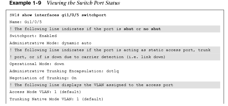
Switch Port Status
Examining the configuration for a switch port can be useful; however, some commands stored elsewhere in the configuration preempt the configuration set on the interface.
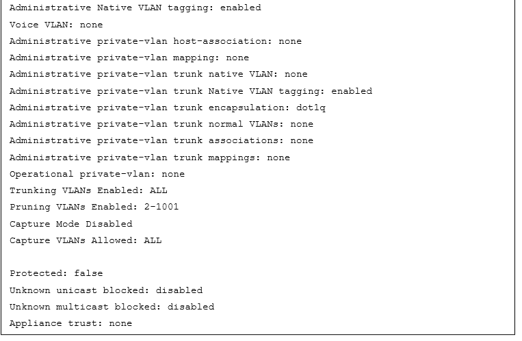
The command show interfaces interface-id switchport provides all the relevant information for a switch port’s status.
The command show interfaces switchport displays the same information for all ports on the switch.
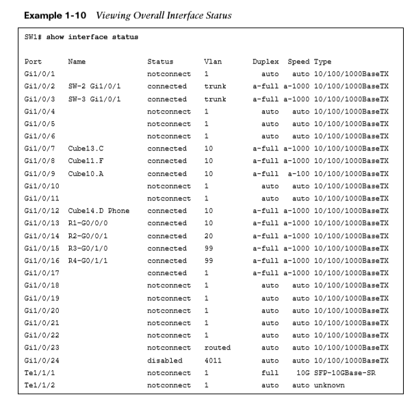
Interface Status
The command show interface status is another useful command for viewing the status of switch ports in a very condensed and simplified manner.
-
Port - Displays the interface ID or port channel.
-
Name - Displays the configured interface description.
-
Status - Displays connected for links where a connection was detected and established to bring up the link. Displays not connect for when a link is not detected and err-disabled when an error has been detected and the switch has disabled the ability to forward traffic out of that port.
-
VLAN - Displays the VLAN number assigned for access ports. Trunk links appear as trunk, and ports configured as Layer 3 interfaces display routed.
-
Duplex - Displays the duplex of the port. If the duplex auto-negotiated, it is prefixed by a-.
-
Speed - Displays the speed of the port. If the port speed was auto-negotiated, it is prefixed by a-.
-
Type - Displays the type of interface for the switch port. If it is a fixed RJ-45 copper port, it includes TX in the description (for example, 10/100/1000BASE-TX). Small form-factor pluggable (SFP)–based ports are listed with the SFP model if there is a driver for it in the software; otherwise, it says unknown.
Layer 3 Forwarding and Local Network Forwarding
Some of the Layer 3 forwarding logic occurs before Layer 2 forwarding. There are two main methodologies for Layer 3 forwarding:
-
Forwarding traffic to devices on the same subnet
-
Forwarding traffic to devices on a different subnet
Local Network forwarding
-
Two devices that reside on the same subnet communicate locally. As the data is encapsulated with its IP address, the device detects that the destination is on the same network. However, the device still needs to encapsulate the Layer 2 information to the packet. It knows its own MAC address but does not initially know the destination’s MAC address.
-
The Address Resolution Protocol (ARP) table provides a method of mapping Layer 3 IP addresses to Layer 2 MAC addresses by storing the IP address of a host and its corresponding MAC address.
-
The ARP table can be viewed with the command show ip arp [mac-address | ip-address | vlan vlan-id | interface-id]. The optional keywords make it possible to filter the information.
Packet Routing
Packets must be routed when two devices are on different networks. As the data is encapsulated with its IP address, a device detects that its destination is on a different network and must be routed. The device checks its local routing table to identify its next-hop IP address, which may be learned in one of several ways:
-
From a static route entry, it can get the destination network, subnet mask, and next-hop IP address.
-
A default-gateway is a simplified static default route that just asks for the local next-hop IP address for all network traffic.
-
Routes can be learned from routing protocols.
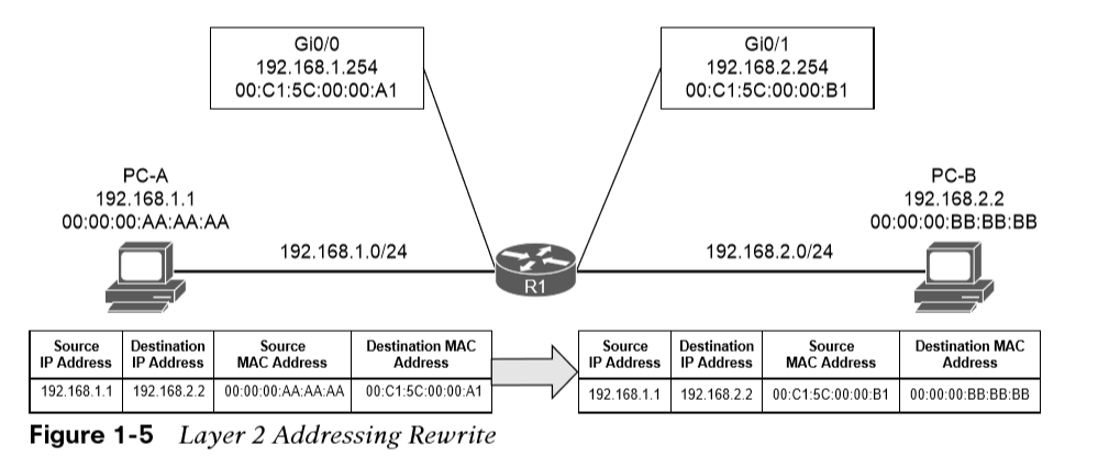
The source device must add the appropriate Layer 2 headers (source and destination MAC addresses), but the destination MAC address is needed for the next-hop IP address.
-
The device looks for the next-hop IP addresses entry in the ARP table and uses the MAC address from the next-hop IP address’s entry as the destination MAC address.
-
The next step is to send the data packet down to Layer 2 for processing and forwarding.
-
The next router receives the packet based on the destination MAC address
-
It analyzes the destination IP address
-
Locates the appropriate network entry in its routing table
-
Identifies the outbound interface
-
Then finds the MAC address for the destination device (or the MAC address for the next-hop address if it needs to be routed further)
-
Finally, the router then modifies the source MAC address to the MAC address of the router’s outbound interface and modifies the destination MAC address to the MAC address for the destination device (or next-hop router).
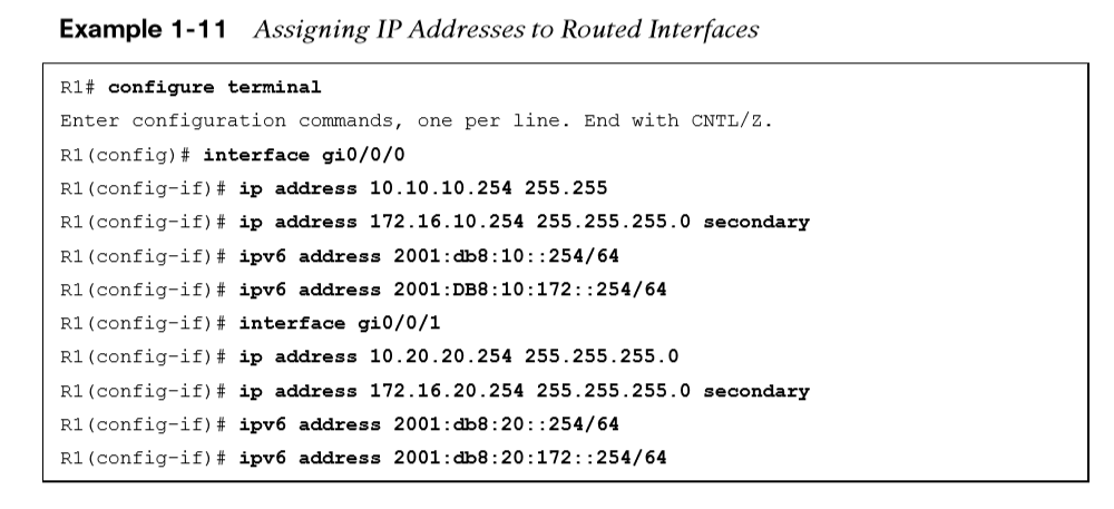
IP Address Assignment
Technologies and mechanisms have been created to allow IPv4 and IPv6 networks to communicate with each other. With either version, an IP address must be assigned to an interface for a router or multilayer switch to route packets.
-
An interface with a configured IP address and that is in an up state injects the associated network into the router’s routing table (Routing Information Base [RIB]).
-
Connected networks or routes have an administrative distance (AD) of zero.
-
It is possible to attach multiple IPv4 networks to the same interface by attaching a secondary IPv4 address to the same interface with the command ip address ip-address subnet-mask secondary.
-
IPv6 addresses are assigned with the interface configuration command ipv6 address ipv6-address/prefix-length.
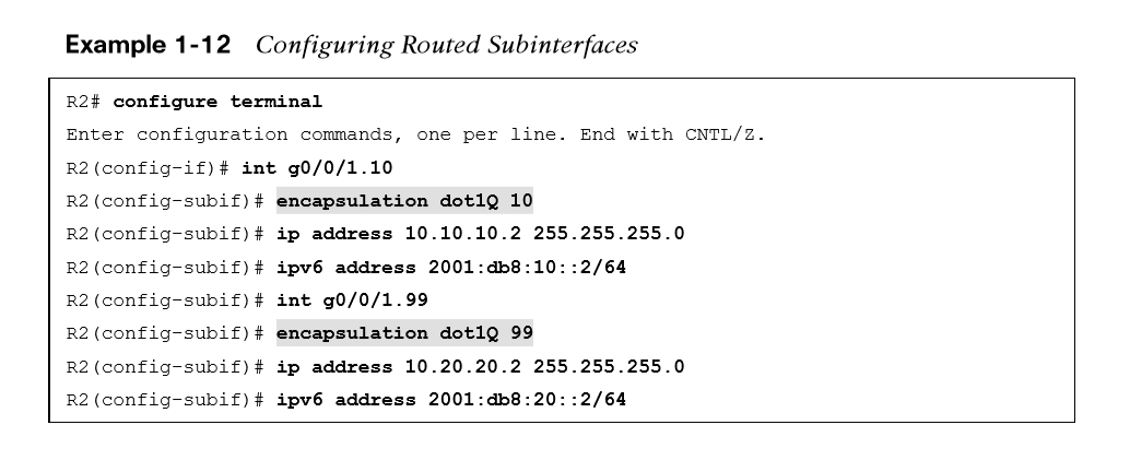
Routed Subinterfaces
It is possible to configuring the switch’s interface as a trunk port and creating logical subinterfaces on a router. A subinterface is created by appending a period and a numeric value after the period. Then the VLAN needs to be associated with the subinterface with the command encapsulation dot1q vlan-id.
Switched Virtual Interfaces
-
With Catalyst switches it is possible to assign an IP address to a switched virtual interface (SVI), also known as a VLAN interface.
-
An SVI is configured by defining the VLAN on the switch and then defining the VLAN interface with the command interface vlan vlan-id.
-
The switch must have an interface associated to that VLAN in an up state for the SVI to be in an up state. If the switch is a multilayer switch, the SVIs can be used for routing packets between VLANs without the need of an external router.

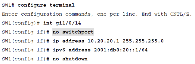
Routed Switchports
Some network designs include a point-to-point link between switches for routing. For example, when a switch needs to connect to a router, some would build a transit VLAN (for example, VLAN 2001), associate the port connecting to the router to VLAN 2001, and then build an SVI for VLAN 2001. There is always the potential that VLAN 2001 could exist elsewhere in the Layer 2 realm or that spanning tree could impact the topology.
Instead, the multilayer switch port can be converted from a Layer 2 switch port to a routed switch port with the interface configuration command no switchport. Then the IP address can be assigned to it.
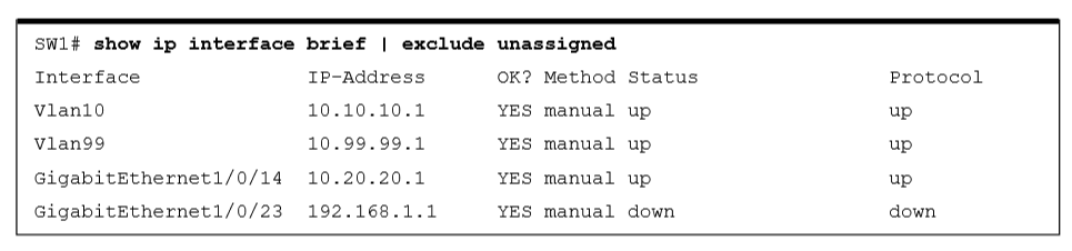
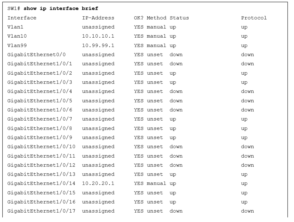
Verification of IP Addresses
IPv4 addresses can be viewed with the command show ip interface [brief | interface-id | vlan vlan-id].
•This command’s output contains: MTU, DHCP relay, ACLs, and the primary IP address.
•The optional brief keyword displays the output in a condensed format.
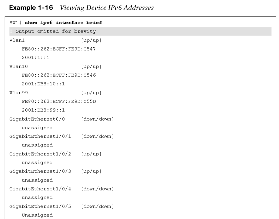
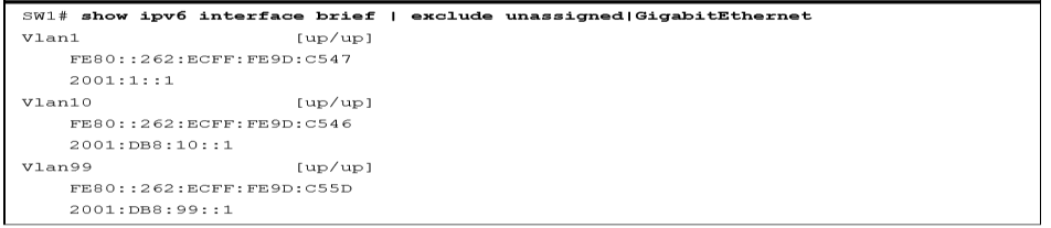
The same information can be viewed for IPv6 addresses with the command show ipv6 interface [brief | interface-id | vlan vlan-id].
Just as with IPv4 addresses, a CLI parser can be used to reduce the information to what is relevant, as demonstrated in Example 1-16.
Forwarding Architectures
-
IP packet switching (or IP packet forwarding) is a process for receiving an IP packet on an input interface and determining whether to forward the packet to an output interface or drop it.
-
Cisco created fast switching and Cisco Express Forwarding (CEF) to optimize the switching process for routers to be able to handle larger packet volumes.
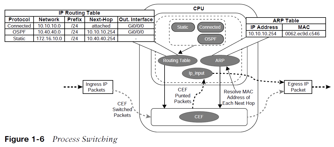
Process Switching
Process switching, also referred to as software switching or slow path, is a switching mechanism in which the general-purpose CPU on a router is in charge of packet switching.
The types of packets that require software handling include the following:
-
Packets sourced or destined to the router (using control traffic or routing protocols)
-
Packets that are too complex for the hardware to handle (IP packets with IP options)
-
Packets that require extra information that is not currently known (e.g., ARP)
Software switching is significantly slower than switching done in hardware. The NetIO process is designed to handle a very small percentage of traffic handled by the system. Packets are hardware switched whenever possible.
The routing table, also known as the Routing Information Base (RIB), is built from information obtained from dynamic routing protocols and directly connected and static routes. The ARP table is built from information obtained from the ARP protocol.
CEF and TCAM
-
Cisco Express Forwarding (CEF) is a Cisco proprietary switching mechanism. It is the default switching mechanism used by all Cisco platforms that use specialized application-specific integrated circuits (ASICs) and network processing units (NPUs) for high packet throughput (hardware-based routers).
-
A switch’s ternary content addressable memory (TCAM) allows for the matching and evaluation of a packet on more than one field.
-
The TCAM entries are stored in Value, Mask, and Result (VMR) format. The value indicates the fields that should be searched, such as the IP address and protocol fields. The mask indicates the field that is of interest and that should be queried. The result indicates the action that should be taken with a match on the value and mask.
-
TCAM operates in hardware, providing faster processing and scalability than process switching.
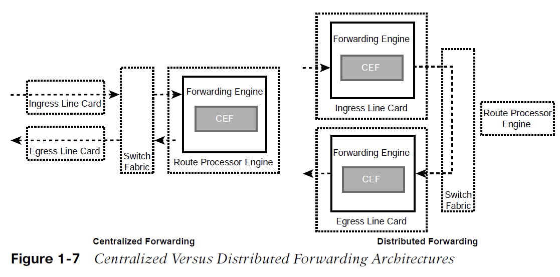
Centralized Forwarding and Distributed Forwarding
-
When a route processor (RP) engine is equipped with a forwarding engine so that it can make all the packet switching decisions, this is known as a centralized forwarding architecture.
-
For a centralized forwarding architecture, when a packet is received on the ingress line card, it is transmitted to the forwarding engine on the RP. The forwarding engine examines the packet’s headers and determines that the packet will be sent out a port on the egress line card and forwards the packet to the egress line card to be forwarded.
-
If the line cards are equipped with forwarding engines so that they can make packet switching decisions without intervention of the RP, this is known as a distributed forwarding architecture.
For a distributed forwarding architecture, when a packet is received on the ingress line card, it is transmitted to the local forwarding engine.
The forwarding engine performs a packet lookup, and if it determines that the outbound interface is local, it forwards the packet out a local interface.
If the outbound interface is located on a different line card, the packet is sent across the switch fabric, also known as the backplane, directly to the egress line card, bypassing the RP.
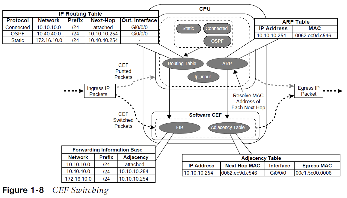
Software CEF
Software CEF, also known as the software Forwarding Information Base, consists of the following components:
-
Forwarding Information Base - The FIB is built directly from the routing table and contains the next-hop IP address for each destination in the network. It keeps a mirror image of the forwarding information contained in the IP routing table. When a routing or topology change occurs in the network, the IP routing table is updated, and these changes are reflected in the FIB. CEF uses the FIB to make IP destination prefix-based switching decisions.
-
Adjacency table - The adjacency table, also known as the Adjacency Information Base (AIB), contains the directly connected next-hop IP addresses and their corresponding next-hop MAC addresses, as well as the egress interface’s MAC address. The adjacency table is populated with data from the ARP table or other Layer 2 protocol tables.
Upon receipt of an IP packet, the FIB is checked for a valid entry.
-
If an entry is missing, it is a “glean” adjacency in CEF, which means the packet should go to the CPU because CEF is unable to handle it.
-
Valid FIB entries continue processing by checking the adjacency table for each packet’s destination IP address.
-
Missing adjacency entries invoke the ARP process. When ARP is resolved, the complete CEF entry can be created.
Hardware CEF
-
ASICs allow for very high packet rates, but they have limited functionality because they are hardwired to perform specific tasks. The routers have NPUs that are designed to overcome the inflexibility of ASICs.
-
NPUs are programmable, and their firmware can be changed easily.
-
Packet switching in distributed architecture platforms is done via distributed CEF (dCEF).
-
dCEF is a mechanism in which the CEF data structures are downloaded to forwarding ASICs and the CPUs of all line cards so that they can participate in packet switching. This means that switching happens at the distributed level, which increases the packet throughput of the router.
Stateful Switchover
-
A route processor (RP) is responsible for learning the network topology and building the route table (RIB).
-
An RP failure can trigger routing protocol adjacencies to reset, resulting in packet loss and network instability. During an RP failure, it may be more desirable to hide the failure and allow the router to continue forwarding packets using the previously programmed CEF table entries rather than temporarily drop packets.
-
Stateful switchover (SSO) is a redundancy feature that allows a Cisco router with two RPs to synchronize router configuration and control plane state information. The process of mirroring information between RPs is referred to as checkpointing. SSO-enabled routers always checkpoint line card operation and Layer 2 protocol states. During a switchover, the standby RP immediately takes control.
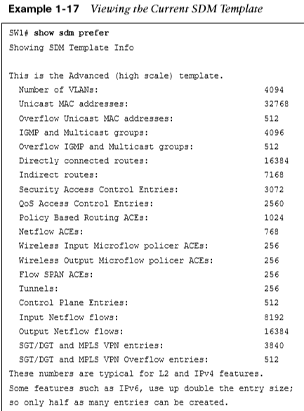
SDM Templates
-
The number of MAC addresses that a switch needs, compared to the number of routes that it holds, depends on where it is deployed in the network. The memory for TCAM tables is statically allocated during the bootup sequence of the switch. When a section of a hardware resource is full, all processing overflow is sent to the CPU. This negatively affects switch performance.
-
The allocation ratios between the various TCAM tables are stored and can be modified with Switching Database Manager (SDM) templates. The SDM template can be configured on Catalyst 9000 switches with the global configuration command sdm prefer {vlan | advanced}. The switch must then be restarted with the reload command.
The current SDM template can viewed with the command show sdm prefer, as demonstrated in Example 1-17.