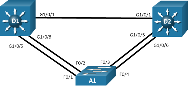
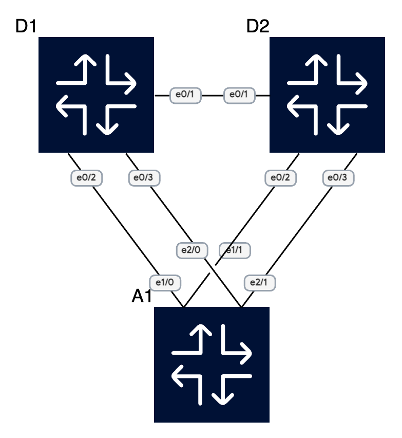
Topology
Addressing Table
| Device | Interface | IPv4 Address |
|---|---|---|
| D1 | VLAN1 | 10.0.0.1/8 |
| D2 | VLAN1 | 10.0.0.2/8 |
| A1 | VLAN1 | 10.0.0.3/8 |
Objectives
Part 1: Build the Network and Configure Basic Device Settings
Part 2: Observe STP Convergence and Topology Change
Part 3: Configure and Verify Rapid Spanning Tree
Background / Scenario
The potential effect of a loop in the Layer 2 network is significant. Layer 2 loops could impact connected hosts as well as the network equipment. Layer 2 loops can be prevented by following good design practices and careful implementation of the Spanning Tree Protocol. In this lab, you will observe the operation of spanning tree protocols to protect the Layer 2 network from loops and topology disruptions. The terms “switch” and “bridge” will be used interchangeably throughout the lab.
Instructions
Part 1: Build the Network and Configure Basic Device Settings and Interface Addressing
In Part 1, you will set up the network topology and configure basic settings and interface addressing on routers.
Step 1: Cable the network as shown in the topology.
Attach the devices as shown in the topology diagram, and cable as necessary.
Step 2: Configure basic settings for each switch.
- Console into each switch, enter global configuration mode, and apply the basic settings and interface addressing. The startup configuration is provided below for each switch in the topology.
Switch D1
...
spanning-tree mode pvst
interface range e0/1-3
	switchport trunk encapsulation dot1q
	switchport mode trunk
	no shutdown
	exit
vlan 2
	name SecondVLAN
	exit
interface vlan 1
	ip address 10.0.0.1 255.0.0.0
	no shut
	exit
Switch D2
...
spanning-tree mode pvst
interface range e0/1-3
	switchport trunk encapsulation dot1q
	switchport mode trunk
	no shutdown
	exit
vlan 2
	name SecondVLAN
	exit
interface vlan 1
	ip address 10.0.0.2 255.0.0.0
	no shut
	exit
Switch A1
...
spanning-tree mode psvt
interface range e1/0-1, e2/0-1
	switchport mode trunk
	no shutdown
	exit
vlan 2
	name SecondVLAN
	exit
interface vlan 1
	ip address 10.0.0.3 255.0.0.0
	no shut
	exit
Part 2: Discover the Default Spanning Tree
Your switches have been configured and interfaces have been enabled, and the Spanning Tree Protocol, operational by default, has already converged onto a loop-free logical network. In this part of the lab, we will discover what that default spanning tree looks like and evaluate why it converged the way it did. We will do this by following the same set of steps that Spanning Tree does. We will find the Root Bridge, then find the Root Ports, and lastly see which ports are Designated ports, and which ports are non-Designated ports in our topology.
Step 1: Find the root bridge.
Our switches are running the Cisco default PVST+, and we have two VLANs in the network, so we should see two root bridges.
- On A1, issue the command show spanning-tree root and observe what the output tells you about the root bridge. Amongst the lab devices being used to document this lab, A1 shows the root id with a cost of 0. This means that A1 is the root bridge.
A1#show spanning-tree root

                                        Root    Hello Max Fwd
Vlan                   Root ID          Cost    Time  Age Dly  Root Port
---------------- -------------------- --------- ----- --- ---  ------------
VLAN0001         32769 aabb.cc00.0100         0    2   20  15
VLAN0002         32770 aabb.cc00.0100         0    2   20  15
- The root bridge is elected based upon which switch has the highest Bridge ID (BID). The BID is made up of a configurable priority value (which defaults to 32768) and the base MAC address for the switch. Use the command show spanning-tree root to gather that information from your switches to support the root bridge decision.
D1#show spanning-tree root

                                        Root    Hello Max Fwd
Vlan                   Root ID          Cost    Time  Age Dly  Root Port
---------------- -------------------- --------- ----- --- ---  ------------
VLAN0001         32769 aabb.cc00.0100       100    2   20  15  Et0/2
VLAN0002         32770 aabb.cc00.0100       100    2   20  15  Et0/2
D2#show spanning-tree root
Root Hello Max Fwd
Vlan Root ID Cost Time Age Dly Root Port
---------------- -------------------- --------- ----- --- --- ------------
VLAN0001 32769 aabb.cc00.0100 100 2 20 15 Et0/2
VLAN0002 32770 aabb.cc00.0100 100 2 20 15 Et0/2The first thing to look at is the priority value. It is 32768 by default. Because we are working with PVST+, a differentiator is added – the priority value is modified with the extended system ID, which is equal to the VLAN number. You can see in the output here that our three devices are using default priorities – 32769 for VLAN 1 (32768 + 1) and 32770 for VLAN 2 (32768 + 2). For each VLAN, the priority values are the same for each of the three switches. When this happens, the rest of the BID is taken into account. The rest of the BID includes the base MAC address. The lowest base MAC address is used to break the tie.
- What are the base MAC addresses for the devices we are using? Issue the command show version | include MAC or show spanning-tree bridge address on each switch.
A1#show spanning-tree bridge  address
VLAN0001         aabb.cc00.0100
VLAN0002         aabb.cc00.0100
D1#show spanning-tree bridge address
VLAN0001 aabb.cc00.0200
VLAN0002 aabb.cc00.0200D2#show spanning-tree bridge address
VLAN0001 aabb.cc00.0300
VLAN0002 aabb.cc00.0300Amongst the three switches being used to document this lab, A1 has the lowest base MAC address. The OUI portion of each MAC address is the same. This is what has caused A1 to be elected as the root bridge.
Step 2: Find the Root Port for each switch.
Each switch will have one single root port. This port represents the lowest path cost to the root bridge. Path Cost is the total of the Port Costs in the path to the root bridge. The Port Cost is based upon the bandwidth value of the port, and it can either be dynamically assigned or statically configured.
- By default, the costs look like this:
- 10 Mbps Ethernet: Cost = 100
- 100 Mbps Fast Ethernet: Cost = 19
- 1 Gbps Gigabit Ethernet: Cost = 4
- 10 Gbps Ten-Gigabit Ethernet: Cost = 2
- These are direct connections to the root, so port cost and path cost are the same. This can be seen in the output of show spanning-tree.
A1#show spanning-tree

VLAN0001
  Spanning tree enabled protocol ieee
  Root ID    Priority    32769
             Address     aabb.cc00.0100
             This bridge is the root
             Hello Time   2 sec  Max Age 20 sec  Forward Delay 15 sec

  Bridge ID  Priority    32769  (priority 32768 sys-id-ext 1)
             Address     aabb.cc00.0100
             Hello Time   2 sec  Max Age 20 sec  Forward Delay 15 sec
             Aging Time  300 sec

Interface           Role Sts Cost      Prio.Nbr Type
------------------- ---- --- --------- -------- --------------------------------
Et0/1               Desg FWD 100       128.2    P2p
Et0/2               Desg FWD 100       128.3    P2p
Et0/3               Desg FWD 100       128.4    P2p
Et1/0               Desg FWD 100       128.5    P2p
Et1/1               Desg FWD 100       128.6    P2p
Et1/2               Desg FWD 100       128.7    P2p
Et1/3               Desg FWD 100       128.8    P2p
Et2/0               Desg FWD 100       128.9    P2p
Et2/1               Desg FWD 100       128.10   P2p
Et2/2               Desg FWD 100       128.11   P2p
Et2/3               Desg FWD 100       128.12   P2p


Interface           Role Sts Cost      Prio.Nbr Type
------------------- ---- --- --------- -------- --------------------------------


VLAN0002
  Spanning tree enabled protocol ieee
  Root ID    Priority    32770
             Address     aabb.cc00.0100
             This bridge is the root
             Hello Time   2 sec  Max Age 20 sec  Forward Delay 15 sec

  Bridge ID  Priority    32770  (priority 32768 sys-id-ext 2)
             Address     aabb.cc00.0100
             Hello Time   2 sec  Max Age 20 sec  Forward Delay 15 sec
             Aging Time  300 sec

Interface           Role Sts Cost      Prio.Nbr Type
------------------- ---- --- --------- -------- --------------------------------
Et0/1               Desg FWD 100       128.2    P2p
Et0/2               Desg FWD 100       128.3    P2p
Et0/3               Desg FWD 100       128.4    P2p
Et1/0               Desg FWD 100       128.5    P2p
Et1/1               Desg FWD 100       128.6    P2p
Et2/0               Desg FWD 100       128.9    P2p
Et2/1 Desg FWD 100 128.10 P2p- Depending on your topology, costs will be different. In this lab the interfaces and just 10Mbps so the cost is 100 and since the switches are directly connected the path cost is the same as the port cost.
Step 3: Identify Designated Ports.
The Spanning Tree Designated Port can be traced back to the early versions of the protocol, which were developed when LAN segments were shared, multiaccess networks. In these networks, there was a very real possibility that there could be users attached to a segment between two switches.
The job of the Designated Port back then was to ensure that users had a way to access the network from a given segment, and there was always one Designated Port on each segment. In the switched networks of today, there are very few shared segments, so the job of the Designated Port is more to help maintain the network topology.
A Designated Port stays active in the topology, both sending BPDUs and learning MAC addresses. Every port on the Root Bridge is a Designated Port. Further, there is one Designated Port on every segment that is not attached directly to the root.
D1#show spanning-tree vlan 2

VLAN0002
  Spanning tree enabled protocol ieee
  Root ID    Priority    32770
             Address     aabb.cc00.0100
             Cost        100
             Port        3 (Ethernet0/2)
             Hello Time   2 sec  Max Age 20 sec  Forward Delay 15 sec

  Bridge ID  Priority    32770  (priority 32768 sys-id-ext 2)
             Address     aabb.cc00.0200
             Hello Time   2 sec  Max Age 20 sec  Forward Delay 15 sec
             Aging Time  300 sec

Interface           Role Sts Cost      Prio.Nbr Type
------------------- ---- --- --------- -------- --------------------------------
Et0/1               Desg FWD 100       128.2    P2p
Et0/2               Root FWD 100       128.3    P2p
Et0/3               Altn BLK 100       128.4    P2p
Interface Et0/3 on D1 is in the Alternate Role, which is the Cisco PVST+ version of the IEEE 802.1D Discarding role. These interfaces are up and receiving BPDUs from the Designated Ports on each segment, but they will not learn MAC addresses or forward traffic until they stop receiving those BDPUs and move to the Designated state.
Part 3: Implement and Observe Rapid Spanning Tree Protocol
In Part 3, you will implement Rapid Spanning Tree Protocol (RSTP) on all the switches. Using the same basic rules, RSTP speeds up convergence significantly.
Try and force a change in the topology, for example, shut down an interface. If you enable debugging for spanning tree events, you’ll see that the whole convergence process takes quite some time, around 20 seconds.
Now let’s change to rapid PVST with:
spanning-tree mode rapid-pvst
Make sure to change to spanning tree mode on all the switches, since they have backwards compatibility with STP, so they won’t update their timers unless all of them are in the same mode.
Try forcing a topology change again. I’m sure you’ll see quite a difference!