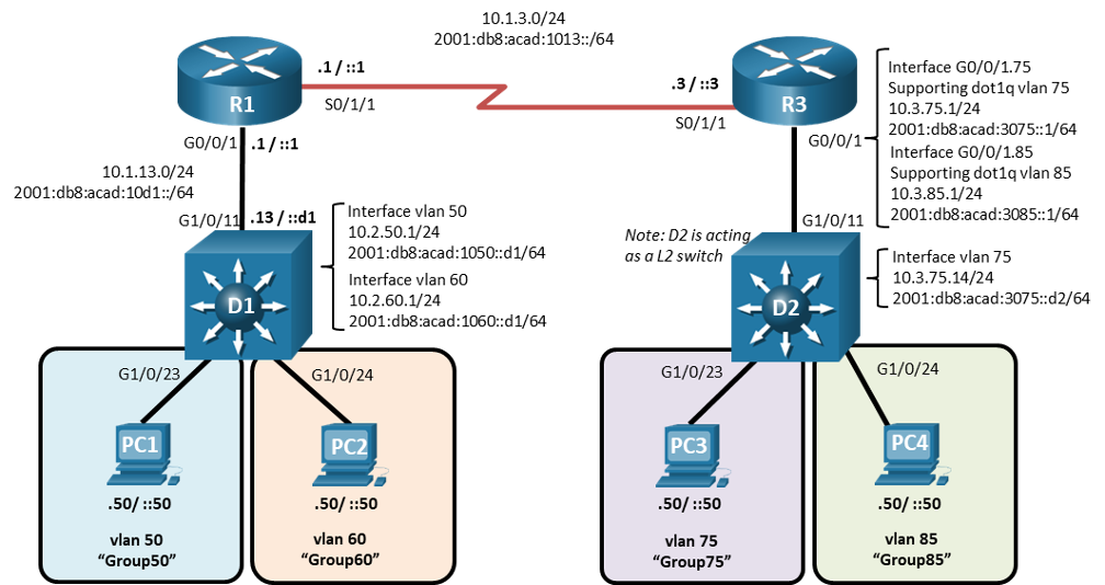
Topology
Addressing Table
| Device | Interface | IPv4 Address | IPv6 Address | IPv6 Link-Local |
|---|---|---|---|---|
| R1 | e0/2 | 10.1.13.1/24 | 2001:db8:acad:10d1::1/64 | fe80::1:1 |
| R1 | e0/1 | 10.1.3.1/24 | 2001:db8:acad:1013::1/64 | fe80::1:2 |
| D1 | e0/1 | 10.1.13.13/24 | 2001:db8:acad:10d1::d1/64 | fe80::d1:1 |
| D1 | VLAN50 | 10.2.50.1/24 | 2001:db8:acad:1050::d1/64 | fe80::d1:2 |
| D1 | VLAN60 | 10.2.60.1/24 | 2001:db8:acad:1060::d1/64 | fe80::d1:3 |
| R3 | e0/1 | 10.1.3.3/24 | 2001:db8:acad:1013::3/64 | fe80::3:1 |
| R3 | e0/2.75 | 10.3.75.1/24 | 2001:db8:acad:3075::1/64 | fe80::3:2 |
| R3 | e0/2.85 | 10.3.85.1/24 | 2001:db8:acad:3085::1/64 | fe80::3:3 |
| D2 | VLAN75 | 10.3.75.14/24 | 2001:db8:acad:3075::d2/64 | fe80::d2:1 |
| PC1 | NIC | 10.2.50.50/24 | 2001:db8:acad:1050::50/64 | EUI-64 |
| PC2 | NIC | 10.2.60.50/24 | 2001:db8:acad:1060::50/64 | EUI-64 |
| PC3 | NIC | 10.3.75.50/24 | 2001:db8:acad:3075::50/64 | EUI-64 |
| PC4 | NIC | 10.3.85.50/24 | 2001:db8:acad:3085::50/64 | EUI-64 |
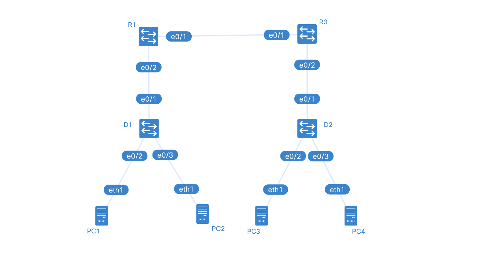
---
title: inter_VLAN_routing
---
graph TD
  D2---PC3
  D2---PC4
  R1---R3
  R1---D1
  D1---PC1
  D1---PC2
  R3---D2
Saving Configuration
ContainerLab doesn’t have a unified config saving feature for now. I’m running a TFTP server on the ContainerLab host and copying the configs to that using this command:
copy running-config tftp://172.20.20.1/clab-inter_VLAN_routing-D1 vrf clab-mgmtYou can reverse that copy to save to and from the TFPT server. You can also change the IP address of the server and the name of the file.
Objectives
Part 1: Build the Network and Configure Basic Device Settings
Part 2: Configure and Verify Inter-VLAN Routing on a Layer 3 Switch
Part 3: Configure and Verify Router-based Inter-VLAN Routing
Part 4: Examine CAM and CEF Details
Background / Scenario
The methods used to move packets and frames from one interface to the next has changed over the years. In this lab you will configure Inter-VLAN Routing in its various forms and then examine the different tables used in making forwarding decisions.
Note: This lab is an exercise in configuring and verifying various methods of Inter-VLAN routing and does not reflect networking best practices.
Note: The routers and switches used with CCNP hands-on labs are Cisco 4221 and Cisco 3650, both with Cisco IOS XE Release 16.9.4 (universalk9 image). Other routers and Cisco IOS versions can be used. Depending on the model and Cisco IOS version, the commands available and the output produced might vary from what is shown in the labs.
Note: Ensure that the routers and switches have been erased and have no startup configurations. If you are unsure contact your instructor.
Instructions
Part 1: Build the Network and Configure Basic Device Settings
In Part 1, you will set up the network topology and configure basic settings.
Step 1: Cable the network as shown in the topology.
Attach the devices as shown in the topology diagram, and cable as necessary.
Step 2: Configure basic settings for each device.
- Console into each router, enter global configuration mode, and apply the basic settings using the following startup configurations.
Router R1 Sample
no ip domain lookup
hostname R1
line con 0
 exec-timeout 0 0
 logging synchronous
 exit
banner motd # This is R1, Inter-VLAN Routing Lab #-
Set the clock on each device to UTC time.
-
Save the running configuration to startup-config.
Part 2: Configure and Verify Inter-VLAN Routing on a Layer 3 Switch
In Part 2, you will configure and verify inter-VLAN Routing on a Layer 3 switch. For this part, you will focus on the configuration of switch D1 and router R1.
Note: The default Switch Database Manager (SDM) template on a Catalyst 3650 running IOS XE supports dual-stacked operations and requires no additional configuration for our purposes.
If you are using an alternate device running Cisco IOS, check the SDM template with the privileged EXEC command show sdm prefer and verify that the ‘number of IPv6 unicast routes’ supported is not zero.
If it is zero, you must change the SDM template to one that supports IPv6 using the sdm prefer template_name global configuration command. The template name will vary depending on the IOS version. Changing the template will require a reboot.
Step 1: On D1, configure Inter-VLAN Routing.
Open configuration window
- Configure D1 to support IP routing and IPv6 unicast routing.
D1(config)# ip routing
D1(config)# ipv6 unicast-routing
2. Create the VLANs and name them as specified in the topology.
D1(config)# vlan 50
D1(config-vlan)# name Group50
D1(config-vlan)# exit
D1(config)# vlan 60
D1(config-vlan)# name Group60
D1(config-vlan)# exit
3. Assign the e0/2 to VLAN 50 and e0/3 to VLAN 60.
D1(config)# interface e0/2
D1(config-if)# switchport mode access
D1(config-if)# switchport access vlan 50
D1(config-if)# no shutdown
D1(config-if)# exit
D1(config)# interface e0/3
D1(config-if)# switchport mode access
D1(config-if)# switchport access vlan 60
D1(config-if)# no shutdown
D1(config-if)# exit
4. Create the Switched Virtual Interfaces (SVI) that will support VLAN 50 and VLAN 60.
D1(config)# interface vlan 50
D1(config-if)# ip address 10.2.50.1 255.255.255.0
D1(config-if)# ipv6 address fe80::d1:2 link-local
D1(config-if)# ipv6 address 2001:db8:acad:1050::d1/64
D1(config-if)# no shutdown
D1(config-if)# exit
D1(config)# interface vlan 60
D1(config-if)# ip address 10.2.60.1 255.255.255.0
D1(config-if)# ipv6 address fe80::d1:3 link-local
D1(config-if)# ipv6 address 2001:db8:acad:1060::d1/64
D1(config-if)# no shutdown
D1(config-if)# exit
5. Configure PC1 with the addresses specified in the Addressing Table. Further assign default gateways of 10.2.50.1 and 2001:db8:acad:1050::d1.
Many ways to do it depending on your chosen platform. As I use containerlab and alpine linux for this lab, I added the following on the *.clab.yml where the linux node is defined:
...
exec:
	- ip addr add 10.2.50.50/24 dev eth1
	- ip route add default via 10.2.50.1 dev eth1
	- ip -6 addr add 2001:db8:acad:1050::50/64 dev eth1
	- ip -6 route add default via 2001:db8:acad:1050::d1 dev eth1
...
6. Configure PC2 with the addresses specified in the Addressing Table. Further assign default gateways of 10.2.60.1 and 2001:db8:acad:1060::d1.
Similar to 5.
7. From PC1, ping PC2’s IPv4 and IPv6 address. Success indicates that D1 is performing Inter-VLAN Routing.
8. Examine the MAC address table on D1 with the command show mac address-table dynamic. You should see PC1 and PC2’s mac addresses listed with the ports they are connected to.
D1#show mac address-table
          Mac Address Table
-------------------------------------------

Vlan    Mac Address       Type        Ports
----    -----------       --------    -----
  50    aac1.abba.1f49    DYNAMIC     Et0/2
  60    aac1.ab0a.58ed    DYNAMIC     Et0/3
Total Mac Addresses for this criterion: 2
Step 2: On D1, configure a routed port and default routes towards R1
- Configure interface e0/1 as a routed port with addressing as specified in the topology diagram.
D1(config)# interface e0/1
D1(config-if)# no switchport
D1(config-if)# ip address 10.1.13.13 255.255.255.0
D1(config-if)# ipv6 address fe80::d1:1 link-local
D1(config-if)# ipv6 address 2001:db8:acad:10d1::d1/64
D1(config-if)# no shutdown
D1(config-if)# exit-
Verify that interface e0/1 is no longer associated with the VLAN database by issuing the command **show vlan brief | i e0/1. There should be no output.
-
Configure static default routes for IPv4 and IPv6 that point towards the interface address at R1.
D1(config)# ip route 0.0.0.0 0.0.0.0 10.1.13.1
D1(config)# ipv6 route ::/0 2001:db8:acad:10d1::1
You may see the error message %ADJ-3-RESOLVE_REQ: Adj resolve request: Failed to resolve 10.1.13.1. This indicates that the switch sent an ARP for the MAC address of 10.1.13.1 and got no reply. We will configure that next.
Step 3: On R1, configure interface addressing and static routing.
- Configure R1 to support IPv6 unicast routing.
R1(config)# ipv6 unicast-routing- Configure the interfaces on R1 with the addresses specified in the Addressing Table.
R1(config)# interface e0/2
R1(config-if)# ip address 10.1.13.1 255.255.255.0
R1(config-if)# ipv6 address fe80::1:1 link-local
R1(config-if)# ipv6 address 2001:db8:acad:10d1::1/64
R1(config-if)# no shutdown
R1(config-if)# exit
R1(config)# interface e0/1
R1(config-if)# ip address 10.1.3.1 255.255.255.0
R1(config-if)# ipv6 address fe80::1:2 link-local
R1(config-if)# ipv6 address 2001:db8:acad:1013::1/64
R1(config-if)# no shutdown
R1(config-if)# exit- Configure routing on R1. Configure static routes to the networks supported by D1 and a default route for everything else point at R3.
R1(config)# ip route 10.2.0.0 255.255.0.0 10.1.13.13
R1(config)# ipv6 route 2001:db8:acad:1050::/64 2001:db8:acad:10d1::d1
R1(config)# ipv6 route 2001:db8:acad:1060::/64 2001:db8:acad:10d1::d1
R1(config)#
R1(config)# ip route 0.0.0.0 0.0.0.0 10.1.3.3
R1(config)#
R1(config)#- From R1, ping PC2 with IPv4 and IPv6. All pings should be successful.
Part 3: Configure and Verify Router-based Inter-VLAN Routing
Step 1: Configure D2 to support the required VLANs.
- Create the VLANs and name them as specified in the topology. In addition, create VLAN 999 and name it NativeVLAN.
D2(config)# vlan 75
D2(config-vlan)# name Group75
D2(config-vlan)# exit
D2(config)# vlan 85
D2(config-vlan)# name Group85
D2(config-vlan)# exit
D2(config)# vlan 999
D2(config-vlan)# name NativeVLAN
D2(config-vlan)# exit-
Assign the e0/2 to VLAN 75 and e0/3 to VLAN 85.
-
Create a Switched Virtual Interface that will operate within VLAN 75.
D2(config)# interface vlan75
D2(config-if)# ip address 10.3.75.14 255.255.255.0
D2(config-if)# ipv6 address fe80::d2:1 link-local
D2(config-if)# ipv6 address 2001:db8:acad:3075::d2/64
D2(config-if)# no shutdown
D2(config-if)# exit- Create an IEEE 802.1Q-based trunk to R3. As a part of the configuration of the trunk, set the native VLAN to VLAN 999 and filter the VLANs allowed on the trunk down to only those that are configured.
D2(config)# interface e0/1
D2(config-if)# switchport trunk encapsulation dot1q
D2(config-if)# switchport mode trunk
D2(config-if)# switchport trunk native vlan 999
D2(config-if)# switchport trunk allowed vlan 75,85,999
D2(config-if)# no shutdown
D2(config-if)# exit
Step 2: Configure R3 to support Inter-VLAN Routing.
-
Configure R3 to support IPv6 unicast routing.
-
Configure the subinterfaces needed on R3 interface e0/2 to support the configured VLANs. Ensure an interface is created for the native VLAN 999.
R3(config)# interface e0/2
R3(config-if)# no shutdown
R3(config-if)# exit
R3(config)# interface e0/2.75
R3(config-subif)# encapsulation dot1q 75
R3(config-subif)# ip address 10.3.75.1 255.255.255.0
R3(config-subif)# ipv6 address fe80::3:2 link-local
R3(config-subif)# ipv6 address 2001:db8:acad:3075::1/64
R3(config-subif)# no shutdown
R3(config-subif)# exit
R3(config)# interface e0/2.85
R3(config-subif)# encapsulation dot1q 85
R3(config-subif)# ip address 10.3.85.1 255.255.255.0
R3(config-subif)# ipv6 address fe80::3:3 link-local
R3(config-subif)# ipv6 address 2001:db8:acad:3085::1/64
R3(config-subif)# no shutdown
R3(config-subif)# exit
R3(config)# interface e0/2.999
R3(config-subif)# encapsulation dot1q 999 native
R3(config-subif)# no shutdown
R3(config-subif)# exit-
Configure PC3 with the addresses specified in the Addressing Table. Further assign default gateways of 10.3.75.1 and 2001:db8:acad:3075::1.
-
Configure PC4 with the addresses specified in the Addressing Table. Further assign default gateways of 10.3.85.1 and 2001:db8:acad:3085::1.
-
From PC3, ping PC4’s IPv4 and IPv6 address. Success indicates that R3 is performing Inter-VLAN Routing.
Step 3: Configure static routing to enable end-to-end reachability.
- On R3, configure interface e0/1 with the addresses specified in the Addressing Table.
R3(config)# interface e0/1
R3(config-if)# ip address 10.1.3.3 255.255.255.0
R3(config-if)# ipv6 address fe80::3:1 link-local
R3(config-if)# ipv6 address 2001:db8:acad:1013::3/64
R3(config-if)# no shutdown
R3(config-if)# exit- On R3, configure a static default route for IPv4 and IPv6 that points to R1’s e0/1 interface addresses.
R3(config)# ip route 0.0.0.0 0.0.0.0 10.1.3.1
R3(config)# ipv6 route ::/0 2001:db8:acad:1013::1
Close configuration window
- On PC3, issue a ping to PC2. The ping should be successful. This indicates the routing solution is working in both directions.
Part 4: Examine CAM and CEF Details
In Part 4, you will examine CEF details on the devices you have configured. The objective of Cisco Express Forwarding is to speed up the process of moving data from one interface to another. To do this, as much data as possible is precompiled into two tables, the Forwarding Information Base (FIB) and the Adjacency Table. These are basically shortcuts that identify what interface a packet should be sent out of and how it should be framed.
- Issue the command show ip cef to see the compiled CEF table, which tells the device what to do with a frame or packet based on its destination address. This table gives the device a quick answer and keeps the CPU from getting directly involved.
R1#show ip cef
Prefix               Next Hop             Interface
0.0.0.0/0            10.1.3.3             Ethernet0/1
0.0.0.0/8            drop
0.0.0.0/32           receive
10.1.3.0/24          attached             Ethernet0/1
10.1.3.0/32          receive              Ethernet0/1
10.1.3.1/32          receive              Ethernet0/1
10.1.3.3/32          attached             Ethernet0/1
10.1.3.255/32        receive              Ethernet0/1
10.1.13.0/24         attached             Ethernet0/2
10.1.13.0/32         receive              Ethernet0/2
10.1.13.1/32         receive              Ethernet0/2
10.1.13.13/32        attached             Ethernet0/2
10.1.13.255/32       receive              Ethernet0/2
10.2.0.0/16          10.1.13.13           Ethernet0/2
127.0.0.0/8          drop
224.0.0.0/4          drop
224.0.0.0/24         receive
240.0.0.0/4          drop
255.255.255.255/32 receive- Issue the command show adjacency, which shows you the address neighbors on each interface.
R1#show adjacency
Protocol Interface                 Address
IP       Ethernet0/0               172.20.20.1(11)
IPV6     Ethernet0/0               3FFF:172:20:20::1(11)
IPV6     Ethernet0/0               FE80::42:F5FF:FEF0:ADA4(2)
IP       Ethernet0/1               10.1.3.3(10)
IPV6     Ethernet0/1               2001:DB8:ACAD:1013::3(7) (incomplete)
IPV6     Ethernet0/1               FE80::3:1(2)
IPV6     Ethernet0/1               FE80::A8C1:ABFF:FEDE:6751(2)
IP       Ethernet0/2               10.1.13.13(10)
IPV6     Ethernet0/2               2001:DB8:ACAD:10D1::D1(11)
IPV6     Ethernet0/2               FE80::D1:1(2)
c. Expand this a bit and issue the command show adjacency detail, and you will see that the router has precompiled the Layer 2 headers and other details to allow it to package information quickly.
R1#show adjacency detail
Protocol Interface                 Address
IP       Ethernet0/0               172.20.20.1(11)
                                   0 packets, 0 bytes
                                   epoch 0
                                   sourced in sev-epoch 0
                                   Encap length 14
                                   0242F5F0ADA4AABBCC0007000800
                                   L2 destination address byte offset 0
                                   L2 destination address byte length 6
                                   Link-type after encap: ip
                                   ARP
IPV6     Ethernet0/0               3FFF:172:20:20::1(11)
                                   0 packets, 0 bytes
                                   epoch 0
                                   sourced in sev-epoch 0
                                   Encap length 14
                                   0242F5F0ADA4AABBCC00070086DD
                                   L2 destination address byte offset 0
                                   L2 destination address byte length 6
                                   Link-type after encap: ipv6
                                   IPv6 ND
IPV6     Ethernet0/0               FE80::42:F5FF:FEF0:ADA4(2)
                                   0 packets, 0 bytes
                                   epoch 0
                                   sourced in sev-epoch 0
                                   Encap length 14
                                   0242F5F0ADA4AABBCC00070086DD
                                   L2 destination address byte offset 0
                                   L2 destination address byte length 6
                                   Link-type after encap: ipv6
                                   IPv6 ND
IP       Ethernet0/1               10.1.3.3(10)
                                   0 packets, 0 bytes
                                   epoch 0
                                   sourced in sev-epoch 0
                                   Encap length 14
                                   AABBCC000810AABBCC0007100800
                                   L2 destination address byte offset 0
                                   L2 destination address byte length 6
                                   Link-type after encap: ip
Protocol Interface                 Address
                                   ARP
IPV6     Ethernet0/1               2001:DB8:ACAD:1013::3(7) (incomplete)
                                   0 packets, 0 bytes
                                   epoch 0
                                   sourced in sev-epoch 0
                                   punt (rate-limited) packets
                                   no src set
IPV6     Ethernet0/1               FE80::3:1(2)
                                   0 packets, 0 bytes
                                   epoch 0
                                   sourced in sev-epoch 0
                                   Encap length 14
                                   AABBCC000810AABBCC00071086DD
                                   L2 destination address byte offset 0
                                   L2 destination address byte length 6
                                   Link-type after encap: ipv6
                                   IPv6 ND
IPV6     Ethernet0/1               FE80::A8C1:ABFF:FEDE:6751(2)
                                   0 packets, 0 bytes
                                   epoch 0
                                   sourced in sev-epoch 0
                                   Encap length 14
                                   AAC1ABDE6751AABBCC00071086DD
                                   L2 destination address byte offset 0
                                   L2 destination address byte length 6
                                   Link-type after encap: ipv6
                                   IPv6 ND
IP       Ethernet0/2               10.1.13.13(10)
                                   0 packets, 0 bytes
                                   epoch 0
                                   sourced in sev-epoch 0
                                   Encap length 14
                                   AABBCC000110AABBCC0007200800
                                   L2 destination address byte offset 0
                                   L2 destination address byte length 6
                                   Link-type after encap: ip
                                   ARP
IPV6     Ethernet0/2               2001:DB8:ACAD:10D1::D1(11)
                                   0 packets, 0 bytes
                                   epoch 0
Protocol Interface                 Address
                                   sourced in sev-epoch 0
                                   Encap length 14
                                   AABBCC000110AABBCC00072086DD
                                   L2 destination address byte offset 0
                                   L2 destination address byte length 6
                                   Link-type after encap: ipv6
                                   IPv6 ND
IPV6     Ethernet0/2               FE80::D1:1(2)
                                   0 packets, 0 bytes
                                   epoch 0
                                   sourced in sev-epoch 0
                                   Encap length 14
                                   AABBCC000110AABBCC00072086DD
                                   L2 destination address byte offset 0
                                   L2 destination address byte length 6
                                   Link-type after encap: ipv6
                                   IPv6 ND