Content
-
EIGRP Fundamentals - This section explains how EIGRP establishes a neighborship with other routers and how routes are exchanged with other routers.
-
EIGRP Configuration Modes - This section defines the two methods of configuring EIGRP with a baseline configuration.
-
Path Metric Calculation - This section explains how EIGRP calculates the path metric to identify the best and alternate loop-free paths.
EIGRP Fundamentals
-
Enhanced Interior Gateway Routing Protocol (EIGRP) is an enhanced distance vector routing protocol commonly found in enterprise networks.
-
EIGRP is a derivative of Interior Gateway Routing Protocol (IGRP) but includes support for variable-length subnet masking (VLSM) and metrics capable of supporting higher-speed interfaces.
-
EIGRP overcomes the deficiencies of other distance vector routing protocols, such as Routing Information Protocol (RIP), with features such as unequal-cost load balancing, support for networks 255 hops away, and rapid convergence features.
-
EIGRP uses a diffusing update algorithm (DUAL) to identify network paths and provides for fast convergence using pre-calculated loop-free backup paths.
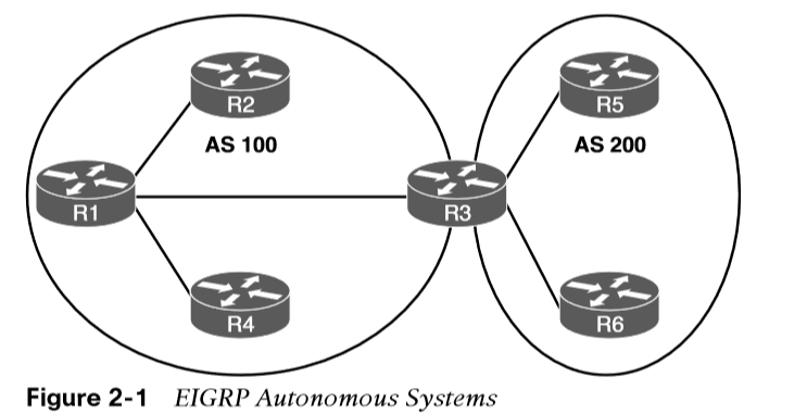
Autonomous Systems
A router can run multiple EIGRP processes. Each process operates under the context of an autonomous system, which represents a common routing domain. Routers within the same domain use the same metric calculation formula and exchange routes only with members of the same autonomous system.
EIGRP uses protocol-dependent modules (PDMs) to support multiple network protocols, such as IPv4, and IPv6. EIGRP is written so that the PDM is responsible for the functions that handle the route selection criteria for each communication protocol. Current versions of EIGRP only support IPv4 and IPv6.
EIGRP Terminology
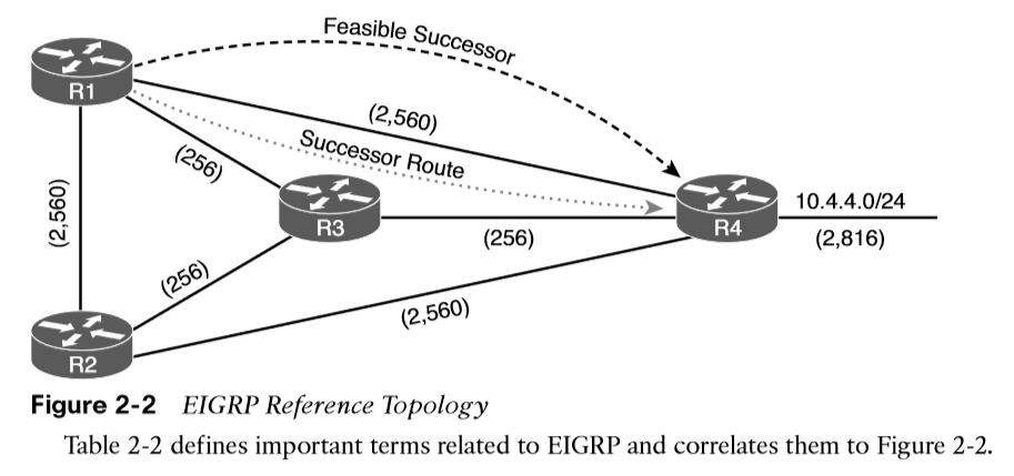
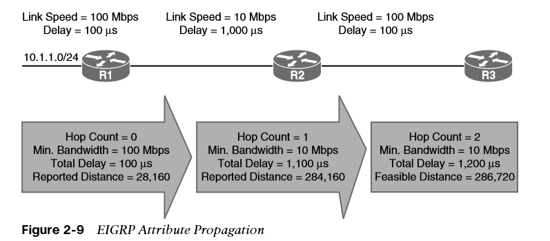
Figure 2-2 is used as a reference topology for R1 calculating the best path and alternative loop-free paths to the 10.4.4.0/24 network. The values in parentheses represent the link’s calculated metric for a segment based on bandwidth and delay.
| Term | Definition |
|---|---|
| Successor route | The route with the lowest path metric to reach a destination. The successor route for R1 to reach 10.4.4.0/24 on R4 is R1→R3→R4. |
| Successor | The first next-hop router for the successor route. The successor for 10.4.4.0/24 is R3. |
| Feasible distance (FD) | The metric value for the lowest-metric path to reach a destination. The feasible distance is calculated locally using the formula shown in the “Path Metric Calculation” section, later in this chapter. The FD calculated by R1 for the 10.4.4.0/24 network is 3328 (that is, 256 + 256 + 2816). |
| Reported distance (RD) | Distance reported by a router to reach a prefix. The reported distance value is the feasible distance for the advertising router. R3 advertises the 10.4.4.0/24 prefix with an RD of 3072. R4 advertises the 10.4.4.0/24 to R1 and R2 with an RD of 2816. |
| Feasibility condition | For a route to be considered a backup route, the RD received for that route must be less than the FD calculated locally. This logic guarantees a loop-free path. |
| Feasible successor | A route with that satisfies the feasibility condition is maintained as a backup route. The feasibility condition ensures that the backup route is loop free. The route R1→R4 is the feasible successor because the RD of 2816 is lower than the FD of 3328 for the R1→R3→R4 path. |
EIGRP Topology Table
EIGRP contains a topology table, which makes it different from a true distance vector routing protocol. EIGRP’s topology table is a vital component of DUAL and contains information to identify loop-free backup routes. The topology table contains all the network prefixes advertised within an EIGRP autonomous system.
Each entry in the table contains the following:
- Network prefix
- EIGRP neighbors that have advertised that prefix
- Metrics from each neighbor (reported distance and hop count)
- Values used for calculating the metric (load, reliability, total delay, and minimum bandwidth)
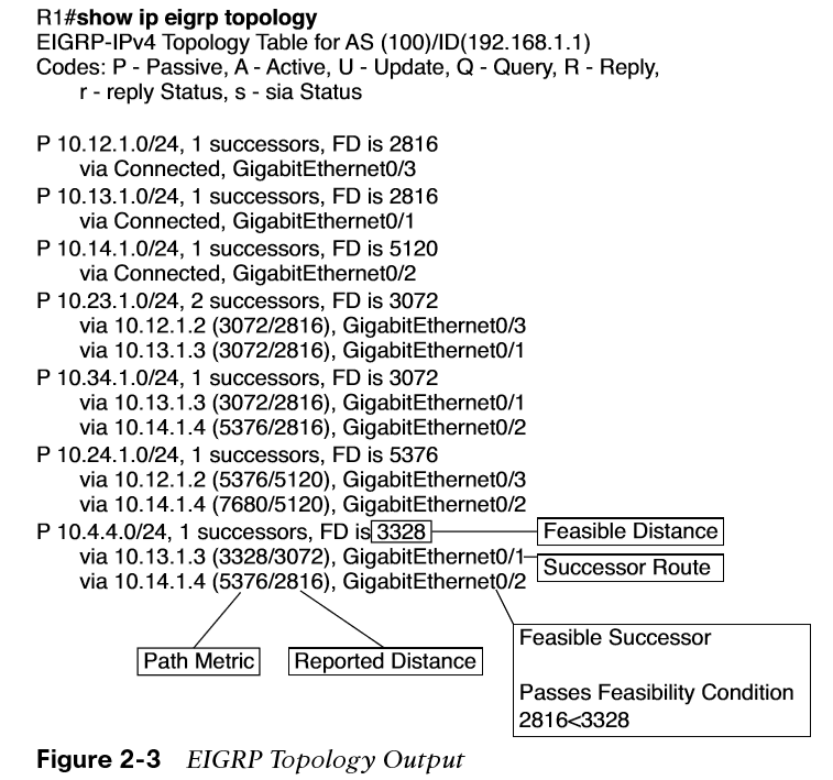
The command show ip eigrp topology shows only the successor and feasible successor routes, as shown in Figure 2-3, the optional all-linkskeyword shows all paths received.
EIGRP Neighbors
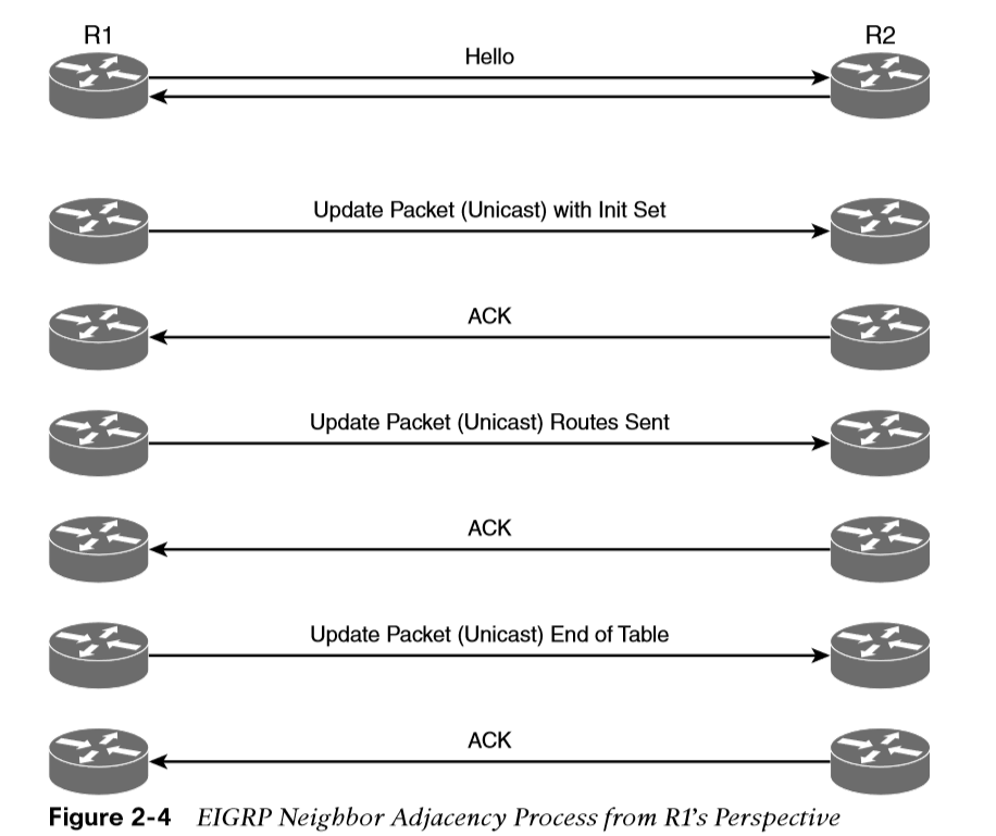
EIGRP does not rely on periodic advertisement of all the network prefixes in an autonomous system, which is done with routing protocols such as Routing Information Protocol (RIP), Open Shortest Path First (OSPF), and Intermediate System-to-Intermediate System (IS-IS). EIGRP neighbors exchange the entire routing table when forming an adjacency, and they advertise incremental updates only as topology changes occur within a network.
The neighbor adjacency table is vital for tracking neighbor status and the updates sent to each neighbor.
Inter-Router Communication
-
EIGRP uses five different packet types to communicate with other routers, as shown in Table 2-3.
-
EIGRP uses its own IP protocol number (88) and uses multicast packets where possible; it uses unicast packets when necessary.
-
Communication between routers is done with multicast using the group address 224.0.0.10 or the MAC address 01:00:5e:00:00:0a when possible.
-
EIGRP uses multicast packets to reduce bandwidth consumed on a link (one packet to reach multiple devices).
-
EIGRP uses Reliable Transport Protocol (RTP) to ensure that packets are delivered in order and to ensure that routers receive specific packets. A sequence number is included in each EIGRP packet. The sequence value zero does not require a response from the receiving EIGRP router; all other values require an ACK packet that includes the original sequence number.
Table 2-3 EIGRP Packet Types
| Packet Type | Packet Name | Function |
|---|---|---|
| 1 | Hello | Used for discovery of EIGRP neighbors and for detecting when a neighbor is no longer available |
| 2 | Request | Used to get specific information from one or more neighbors |
| 3 | Update | Used to transmit routing and reachability information with other EIGRP neighbors |
| 4 | Query | Sent out to search for another path during convergence |
| 5 | Reply | Sent in response to a query packet |
Forming EIGRP Neighbors
Unlike other distance vector routing protocols, EIGRP requires a neighbor relationship to form before routes are processed and added to the Routing Information Base (RIB). Upon hearing an EIGRP hello packet, a router attempts to become the neighbor of the other router.
The following parameters must match for the two routers to become neighbors:
- Metric formula K values
- Primary subnet matches
- Autonomous system number (ASN) matches
- Authentication parameters
EIGRP Configuration Modes
- The two methods of EIGRP configuration are classic mode and named mode.
Classic Configuration Mode
With classic EIGRP configuration mode, most of the configuration takes place in the EIGRP process, but some settings are configured under the interface configuration submode. This can add complexity for deployment and troubleshooting as users must scroll back and forth between the EIGRP process and individual network interfaces. Some of the settings that are set individually are hello advertisement interval, split-horizon, authentication, and summary route advertisements.
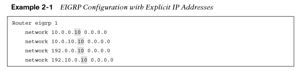
Classic configuration requires the initialization of the routing process with the global configuration command router eigrp as-number to identify the ASN and initialize the EIGRP process. The second step is to identify the network interfaces with the command network ip-address [mask].
EIGRP Named Mode
EIGRP named mode configuration was released to overcome some of the difficulties network engineers have with classic EIGRP autonomous system configuration, including scattered configurations and unclear scope of commands.
EIGRP named configuration provides the following benefits:
- All the EIGRP configuration occurs in one location.
- It supports current EIGRP features and future developments.
- It supports multiple address families (including Virtual Routing and Forwarding [VRF] instances). EIGRP named configuration is also known as multi-address family configuration mode.
- Commands are clear in terms of the scope of their configuration.
EIGRP named configuration makes it possible to run multiple instances under the same EIGRP process. EIGRP named mode provides a hierarchical configuration and stores settings in three subsections:
-
Address Family - This submode contains settings that are relevant to the global EIGRP AS operations, such as selection of network interfaces, EIGRP K values, logging settings, and stub settings.
-
Interface - This submode contains settings that are relevant to the interface, such as hello advertisement interval, split-horizon, authentication, and summary route advertisements. In actuality, there are two methods of the EIGRP interface section’s configuration. Commands can be assigned to a specific interface or to a default interface, in which case those settings are placed on all EIGRP-enabled interfaces. If there is a conflict between the default interface and a specific interface, the specific interface takes priority over the default interface.
-
Topology - This submode contains settings regarding the EIGRP topology database and how routes are presented to the router’s RIB. This section also contains route redistribution and administrative distance settings.
EIGRP Network Statement
Both configuration modes use a network statement to identify the interfaces that EIGRP will use. The network statement uses a wildcard mask, which allows the configuration to be as specific or ambiguous as necessary.
 The syntax for the network statement, which exists under the EIGRP process, is network ip-address [mask]. The optional mask can be omitted to enable interfaces that fall within the classful boundaries for that network statement.
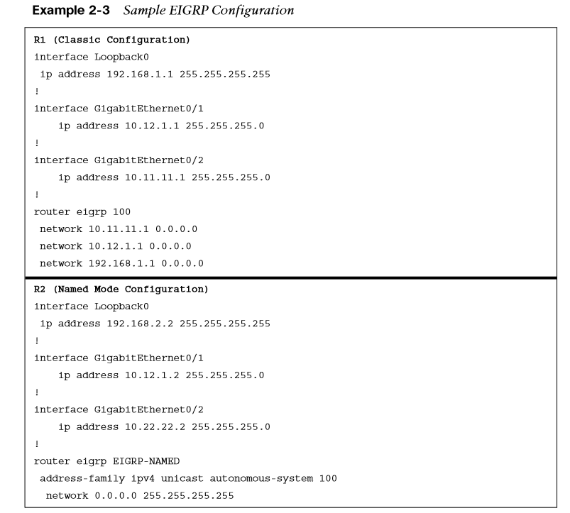
Sample Topology and Configuration
Figure 2-5 shows a sample topology for demonstrating EIGRP configuration in classic mode for R1 and named mode for R2.
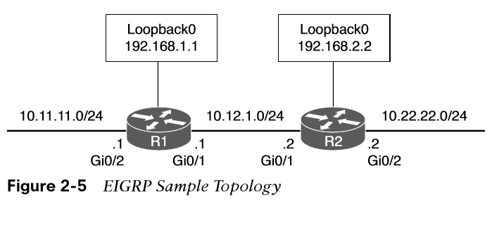
Example 2-3 provides the configuration that is applied to R1 and R2.
Confirming Interfaces
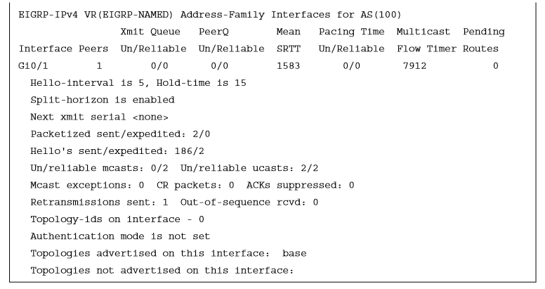
After configuration, it is a good practice to verify that only the intended interfaces are running EIGRP. The command show ip eigrp interfaces [{interface-id [detail] | detail}] shows active EIGRP interfaces.
Appending the optional detail keyword provides additional information, such as authentication, EIGRP timers, split horizon, and various packet counts.
Example 2-5 demonstrates R1’s non-detailed EIGRP interface and R2’s detailed information for the gi0/1 interface.
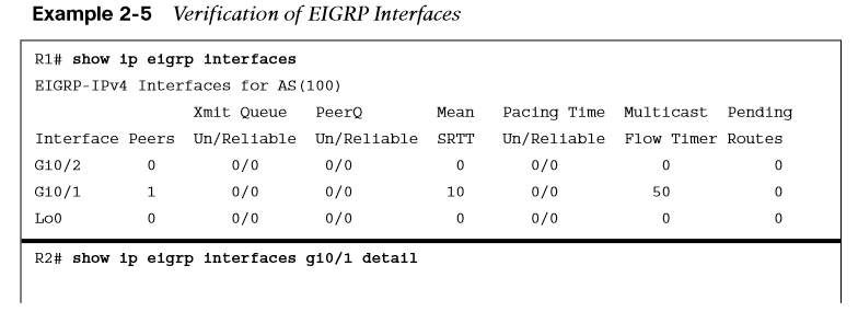
| Term | Description |
|---|---|
| Interface | Interfaces running EIGRP. |
| Peers | Number of peers detected on that interface. |
| Xmt Queue Un/Reliable | Number of unreliable/reliable packets remaining in the transmit queue. The value zero is an indication of a stable network. |
| Mean SRTT | Average time for a packet to be sent to a neighbor and a reply from that neighbor to be received, in milliseconds. |
| Multicast Flow Timer | Maximum time (seconds) that the router sent multicast packets |
| Pending Routes | Number of routes in the transmit queue that need to be sent. |
Verifying EIGRP Neighbor Adjacencies
Each EIGRP process maintains a table of neighbors to ensure that they are alive and processing updates properly. Without keeping track of a neighbor state, an autonomous system could contain incorrect data and could potentially route traffic improperly. EIGRP must form a neighbor relationship before a router advertises update packets containing network prefixes.
The command show ip eigrp neighbors [interface-id] displays the EIGRP neighbors for a router. Example 2-6 shows the EIGRP neighbor information using this command.
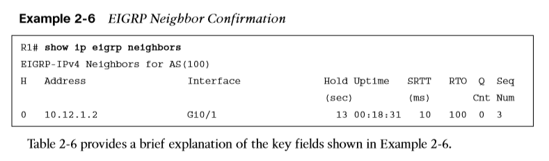
| Field | Description |
|---|---|
| Address | IP address of the EIGRP neighbor |
| Interface | Interface the neighbor was detected on |
| Holdtime | Time left to receive a packet from this neighbor to ensure it is still alive |
| SRTT | Time for a packet to be sent to a neighbor and reply to be received from that neighbor in milliseconds |
| RTO | Timeout for retransmission (waiting for ACK) |
| Q cnt | Number of packets (update/query/reply) in queue for sending |
| Seq Num | Sequence number that was last received from the router |
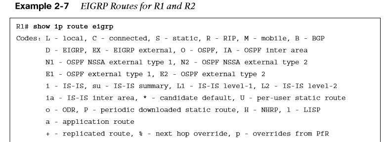
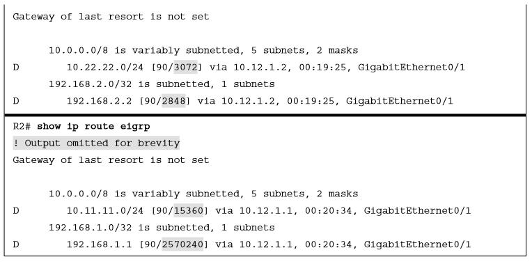
Displaying Installed EIGRP Routes
You can see EIGRP routes that are installed into the RIB by using the command show ip route eigrp.
-
EIGRP routes originating within the autonomous system have an administrative distance (AD) of 90 and are indicated in the routing table with a D.
-
Routes that originate from outside the autonomous system are external EIGRP routes
-
External EIGRP routes have an AD of 170 and are indicated in the routing table with D EX.
-
Placing external EIGRP routes into the RIB with a higher AD acts as a loop-prevention mechanism.
Example 2-7 displays the EIGRP routes from the sample topology in Figure 2-5. The metric for the selected route is the second number in brackets.
Router ID
-
The router ID (RID) is a 32-bit number that uniquely identifies an EIGRP router and is used as a loop-prevention mechanism.
-
The RID can be set dynamically, which is the default, or manually.
-
The algorithm for dynamically choosing the EIGRP RID uses the highest IPv4 address of any up loopback interfaces. If there are not any up loopback interfaces, the highest IPv4 address of any active up physical interfaces becomes the RID when the EIGRP process initializes.
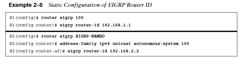 You use the command eigrp router-id to set the RID, as demonstrated in Example 2-8, for both classic and named mode configurations.
Passive Interfaces
Some network topologies must advertise a network segment into EIGRP but need to prevent neighbors from forming adjacencies with other routers on that segment. In this scenario, you need to put the EIGRP interface in a passive state. Passive EIGRP interfaces do not send out or process EIGRP hellos, which prevents EIGRP from forming adjacencies on that interface.
To configure an EIGRP interface as passive, you use the command passive-interface interface-id under the EIGRP process for classic configuration.
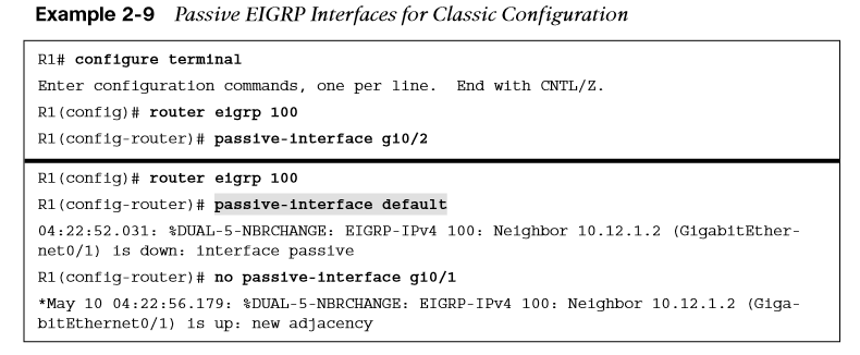 Example 2-9 demonstrates making R1’s gi0/2 interface passive and also the alternative option of making all interfaces passive but setting gi0/1 as non-passive.
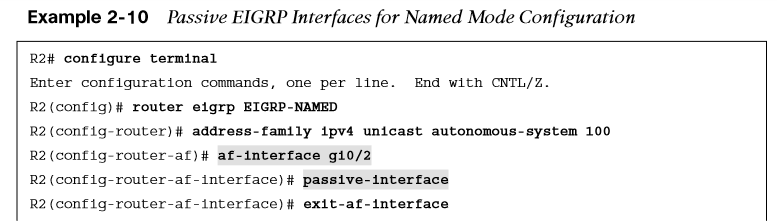
For a named mode configuration, you place the passive-interface state on af-interface default for all EIGRP interfaces or on a specific interface with the af-interface interface-id section. Example 2-10 shows how to set the gi0/2 interface as passive while allowing the gi0/1 interface to be active using both configuration strategies.
The command show ip protocols provides valuable information about all the routing protocols. With EIGRP, it displays the EIGRP process identifier, the ASN, K values that are used for path calculation, RID, neighbors, AD settings, and all the passive interfaces.
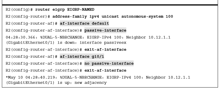 Example 2-11 shows what the named mode configuration looks like with some settings (i.e. passive-interface or no passive-interface) placed under the af-interface default or the af-interface interface-id setting.
Authentication
-
Authentication is a mechanism for ensuring that only authorized routers are eligible to become EIGRP neighbors.
-
Authentication prevents adding a router to a network and introducing invalid routes, accidentally or maliciously.
-
A precomputed password hash is included with all EIGRP packets, and when the packet is received, the receiving router also calculates the hash on the packet. If the two hash values match, the packet is accepted.
-
EIGRP encrypts the password by using a Message Digest 5 (MD5) authentication, using the keychain function. The hash consists of the key number and a password. EIGRP authentication does not encrypt the contents of the routing update packets.
Keychain creation is accomplished with the following steps:
Step 1. Create the keychain by using the command key chain key-chain-name.
Step 2. Identify the key sequence by using the command key key-number, where _key-number_can be anything from 0 to 2147483647.
Step 3. Specify the preshared password by using the command key-stringpassword.
Enabling Authentication on the Interface
When using classic configuration, authentication must be enabled on the interface under the interface configuration submode. The following commands are used in the interface configuration submode:
- ip authentication key-chain eigrp as-number key-chain-name
- ip authentication mode eigrp as-number md5
The named mode configuration places the configurations under the EIGRP interface submode, under the af-interface default or the af-interfaceinterface-id. Named mode configuration supports MD5 or Hashed Message Authentication Code-Secure Hash Algorithm-256 (HMAC-SHA-256) authentication. MD5 authentication involves the following commands:
- authentication key-chain eigrp key-chain-name
- authentication mode md5
The HMAC-SHA-256 authentication involves the command authentication mode hmacsha-256 password.
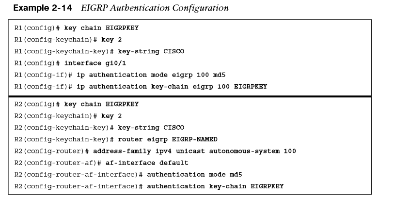 Example 2-14 demonstrates MD5 configuration on R1 with classic EIGRP configuration and on R2 with named mode configuration. Remember that the hash is computed using the key sequence number and key string, which must match on the two nodes.
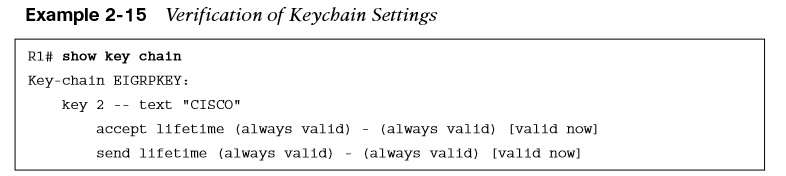
Verification of Keychain Settings
The command show key chain provides verification of the keychain. Example 2-15 shows that each key sequence provides the lifetime and password.
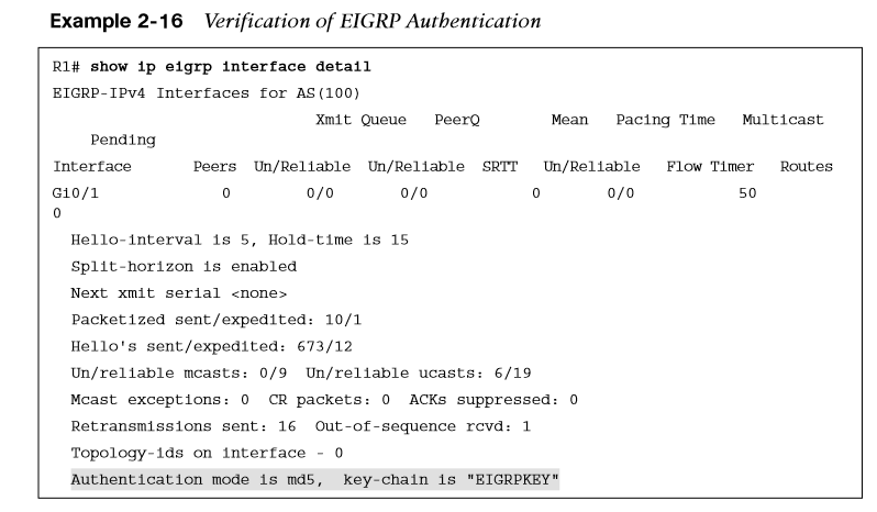
Example 2-16 provides detailed EIGRP interface output.
Path Metric Calculation
-
Metric calculation is a critical component for any routing protocol.
-
EIGRP uses multiple factors to calculate the metric for a path.
-
Metric calculation uses bandwidth and delay by default but can include interface load and reliability, too.
EIGRP Classic Metric Formula
EIGRP uses K values to define which factors the formula uses and the impact associated with a factor when calculating the metric. BW represents the slowest link in the path, scaled to a 10 Gbps link (107). Link speed is collected from the configured interface bandwidth on an interface. Delay is the total measure of delay in the path, measured in tens of microseconds (μs).
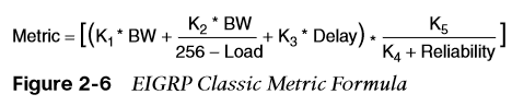 The formula shown in Figure 2-6 illustrates the EIGRP classic metric formula.
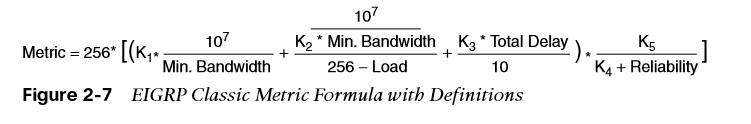
The EIGRP formula is based on the IGRP metric formula, except the output is multiplied by 256 to change the metric from 24 bits to 32 bits. Taking these definitions into consideration, the formula for EIGRP is shown in Figure 2-7.
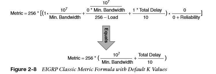
 By default, K1 and K3 have a value of 1, and K2, K4, and K5 are set to 0. Figure 2-8 places default K values into the formula and shows a streamlined version of the formula.
EIGRP Attribute Propagation
The EIGRP update packet includes path attributes associated with each prefix. The EIGRP path attributes can include hop count, cumulative delay, minimum bandwidth link speed, and RD. The attributes are updated each hop along the way, allowing each router to independently identify the shortest path.
Figure 2-9 shows the information in the EIGRP update packets for the 10.1.1.0/24 prefix propagating through the autonomous system. Notice that as the hop count increments, minimum bandwidth decreases, total delay increases, and the RD changes with each EIGRP update.
Default EIGRP Interface Metrics for Classic Metrics
Table 2-7 shows some of the common network types, link speeds, delay, and EIGRP metric, using the streamlined formula from Figure 2-7.
| Interface Type | Link Speed (Kbps) | Delay | Metric |
|---|---|---|---|
| Serial | 64 | 20,000 μs | 40,512,000 |
| T1 | 1544 | 20,000 μs | 2,170,031 |
| Ethernet | 10,000 | 1000 μs | 281,600 |
| Fast Ethernet | 100,000 | 100 μs | 28,160 |
| GigabitEthernet | 1,000,000 | 10 μs | 2816 |
| TenGigabitEthernet | 10,000,000 | 10 μs | 512 |
If you are unsure of the EIGRP metrics, you can query the parameters for the formula directly from EIGRP’s topology table by using the command show ip eigrp topology network/prefix-length.
Wide Metrics
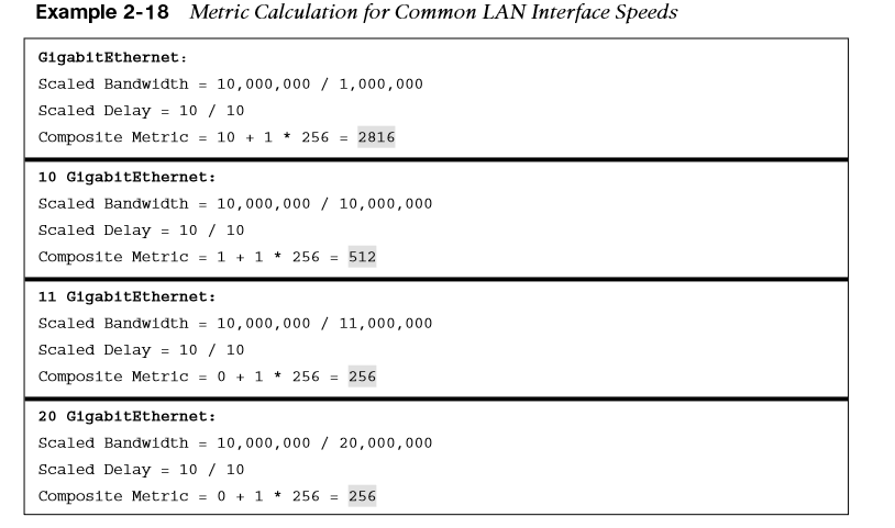
Example 2-18 provides some metric calculations for common LAN interface speeds. Notice that there is not a differentiation between an 11 Gbps interface and a 20 Gbps interface. The composite metric stays at 256, despite the different bandwidth rates.
EIGRP includes support for a second set of metrics, known as wide metrics, that addresses the issue of scalability with higher-capacity interfaces.
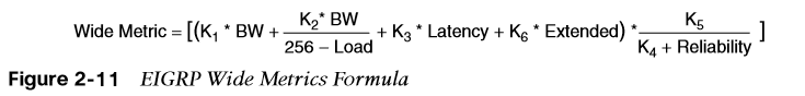
Figure 2-11 shows the explicit EIGRP wide metrics formula. Notice that an additional K value (K6) is included that adds an extended attribute to measure jitter, energy, or other future attributes.
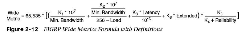
Just as EIGRP scaled by 256 to accommodate IGRP, EIGRP wide metrics scale by 65,535 to accommodate higher-speed links. This provides support for interface speeds up to 655 terabits per second (65,535 .107) without any scalability issues.
Latency is the total interface delay measured in picoseconds () instead of in microseconds (). Figure 2-12 shows an updated formula that takes into account the conversions in latency and scalability.
The EIGRP classic metrics exist only with EIGRP classic configuration, while EIGRP wide metrics exist only in EIGRP named mode. The metric style used by a router is identified with the command show ip protocols; if a K6 metric is present, the router is using wide-style metrics.
Metric Backward Compatibility
EIGRP wide metrics were designed with backward compatibility in mind. EIGRP wide metrics set K2 and K3 to a value of 1 and set K2, K4, K5, and K6 to 0, which allows backward compatibility because the K value metrics match with classic metrics. As long as K1 through K5 are the same and K6 is not set, the two metric styles allow adjacency between routers.
EIGRP is able to detect when peering with a router is using classic metrics, and it unscales the metric to the formula in Figure 2-13.
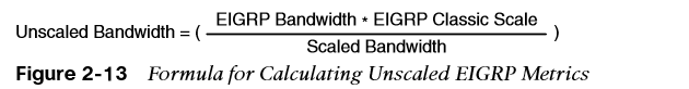
This conversion results in loss of clarity if routes pass through a mixture of classic metric and wide metric devices. It is best to keep all devices operating with the same metric style.
Interface Delay Settings
Example 2-20 provides sample output of the command on R1 and R2. Both interfaces have a delay of 10.
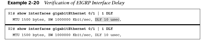
EIGRP delay is set on an interface-by-interface basis, allowing for manipulation of traffic patterns flowing through a specific interface on a router. Delay is configured with the interface parameter command delay tens-of-microseconds under the interface.
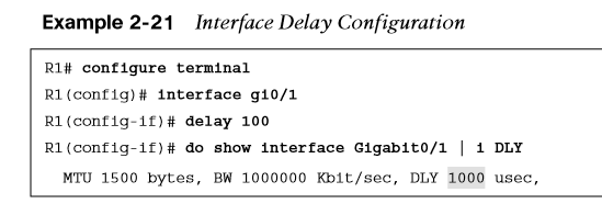
Example 2-21 demonstrates the modification of the delay on R1 to 100, increasing the delay to 1000 μs on the link between R1 and R2. To ensure consistent routing, modify the delay on R2’s gi0/1 interface as well, then verify the change.
Custom K Values
If the default metric calculations are insufficient, you can change them to modify the path metric formula.
-
K values for the path metric formula are set with the command metric weights TOS under the EIGRP process.
-
The TOS value always has a value of 0, and the K6 value is used for named mode configurations.
-
To ensure consistent routing logic in an EIGRP autonomous system, the K values must match between EIGRP neighbors to form an adjacency and exchange routes.
-
The K values are included as part of the EIGRP hello packet.
The K values are displayed with the show ip protocols command.
Load Balancing
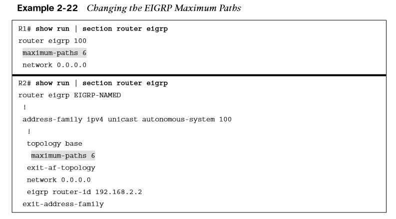
EIGRP allows multiple successor routes (with the same metric) to be installed into the RIB. Installing multiple paths into the RIB for the same prefix is called equal-cost multipathing (ECMP) routing. The default maximum ECMP is four routes. You change the default ECMP setting with the command maximum-paths under the EIGRP process in classic mode and under the topology base submode in named mode.
Example 2-22 shows the configuration for changing the maximum paths on R1 and R2 so that classic and named mode configurations are visible.
EIGRP supports unequal-cost load balancing, which allows installation of both successor routes and feasible successors into the EIGRP RIB. To use unequal-cost load balancing with EIGRP, change EIGRP’s variance multiplier. The EIGRP variance value is the feasible distance (FD) for a route multiplied by the EIGRP variance multiplier. Any feasible successor’s FD with a metric below the EIGRP variance value is installed into the RIB.
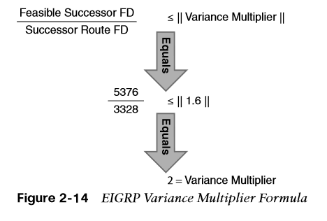
Dividing the feasible successor metric by the successor route metric provides the variance multiplier. The variance multiplier is a whole number, and any remainders should always round up.