Content
-
Failure Detection and Timers - This section explains how EIGRP detects the absence of a neighbor and the convergence process.
-
Route Summarization - This section explains the logic and configuration of summarizing routes on a router.
-
WAN Considerations - This section reviews common design considerations with using EIGRP in a WAN.
-
Route Manipulation - This section explains techniques for filtering or manipulating route metrics.
Failure Detection and Timers
-
A secondary function of the EIGRP hello packets is to ensure that EIGRP neighbors are still healthy and available. EIGRP hello packets are sent out in intervals according to the hello timer.
-
The hold timer is the amount of time EIGRP deems the router reachable and functioning. The hold time value defaults to three times the hello interval.
-
The hold time decrements, and upon receipt of a hello packet, the hold time resets and restarts the countdown.
-
If the hold time reaches 0, EIGRP declares the neighbor unreachable and notifies the diffusing update algorithm (DUAL) of a topology change.
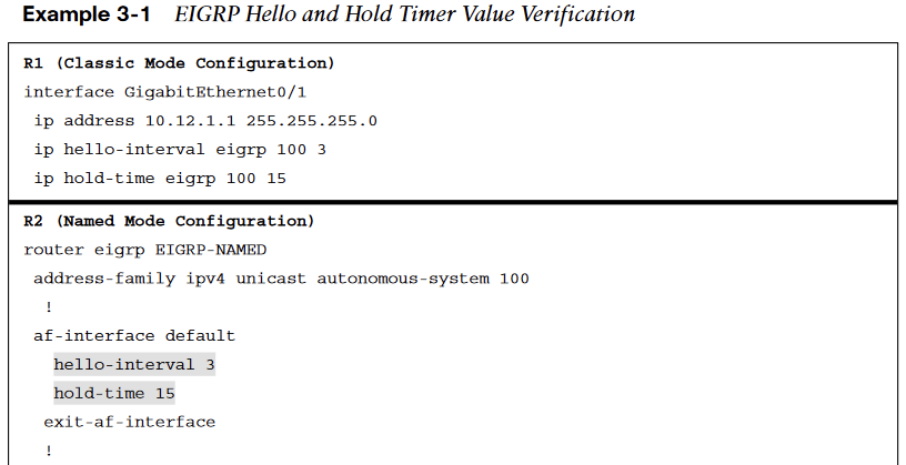
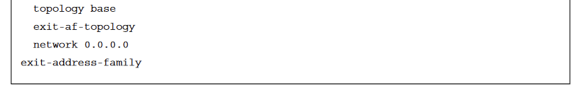
EIGRP Hello and Hold Timer Value Verification
-
The hello timer is modified with the interface command ip hello-interval eigrp as-number seconds, and the hold timer is modified with the command ip hold-time eigrp as-number seconds when using EIGRP classic configuration mode.
-
The EIGRP hello and hold timers are verified by viewing the EIGRP interfaces with the command show ip eigrp interfaces detail [interface-id].
-
Example 3-1 demonstrates changing the EIGRP hello interval to 3 seconds and the hold time to 15 seconds for R1.
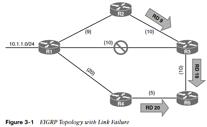
Convergence
When EIGRP detects that it has lost its successor for a path, the feasible successor instantly becomes the successor route, providing a backup route.
The router sends out an update packet for that path because of the new EIGRP path metrics.
Downstream routers run their own DUAL algorithm for any affected prefixes to account for the new EIGRP metrics.
Figure 3-1 demonstrates such a scenario when the link between R1 and R3 fails.
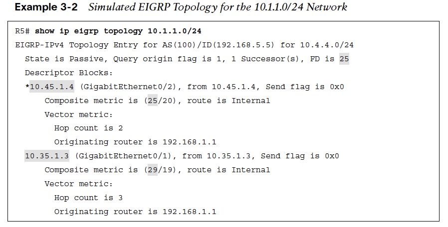
EIGRP Topology
Example 3-2 provides simulated output of R5’s EIGRP topology for the 10.1.1.0/24 prefix after the R1–R3 link fails.
EIGRP Query Packets
If a feasible successor is not available for the prefix, DUAL must perform a new route calculation. The route state changes from passive (P) to active (A) in the EIGRP topology table. The router detecting the topology change sends out query packets to EIGRP neighbors for the route. Upon receipt of a query packet, an EIGRP router does one of the following:
-
It replies to the query that the router does not have a route to the prefix.
-
If the query came from the successor for the route, the receiving router detects the delay set for infinity, sets the prefix as active in the EIGRP topology, and sends out a query packet to all downstream EIGRP neighbors for that route.
-
If the query did not come from the successor for that route, it detects that the delay is set for infinity but ignores it because it did not come from the successor. The receiving router replies with the EIGRP attributes for that route.
The query process continues from router to router until a router establishes the query boundary.
A query boundary is established when a router does not mark the prefix as active, meaning that it responds to a query as follows:
-
It says it does not have a route to the prefix.
-
It replies with EIGRP attributes because the query did not come from the successor.
EIGRP Convergence Topology
When a router receives a reply for every downstream query that was sent out, it completes the DUAL, changes the route to passive, and sends a reply packet to any upstream routers that sent a query packet to it.
-
Upon receiving the reply packet for a prefix, the reply packet is notated for that neighbor and prefix.
-
The reply process continues upstream for the queries until the first router’s queries are received.
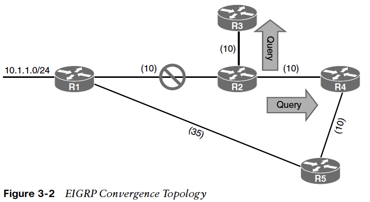
Figure 3-2 shows a topology where the link between R1 and R2 failed.
EIGRP Calculating New Route
The following steps are processed in order from the perspective of R2 calculating a new route to the 10.1.1.0/24 network:
Step 1. R2 detects the link failure. R2 does not have a feasible successor for the route, sets the 10.1.1.0/24 prefix as active and sends queries to R3 and R4.
Step 2. R3 receives the query from R2 and processes the Delay field that is set to infinity. R3 does not have any other EIGRP neighbors and sends a reply to R2 that a route does not exist. R4 receives the query from R2 and processes the Delay field that is set to infinity. Because the query was received by the successor, and a feasible successor for the prefix does not exist, R4 marks the route as active and sends a query to R5.
Step 3. R5 receives the query from R4 and detects that the Delay field is set to infinity. Because the query was received by a non-successor, and a successor exists on a different interface, a reply for the 10.4.4.0/24 network is sent back to R2 with the appropriate EIGRP attributes.
Step 4. R4 receives R5’s reply, acknowledges the packet, and computes a new path. Because this is the last outstanding query packet on R4, R4 sets the prefix as passive. With all queries satisfied, R4 responds to R2’s query with the new EIGRP metrics.
Step 5. R2 receives R4’s reply, acknowledges the packet, and computes a new path. Because this is the last outstanding query packet on R4, R2 sets the prefix as passive.
Stuck in Active
EIGRP maintains a timer called “active timer” which has a default value of 3 minutes (180 seconds). EIGRP waits half of the active timer value (90 seconds) for a reply. If the router does not receive a response within 90 seconds, the originating router sends a stuck in active (SIA) query to EIGRP neighbors that did not respond.
Upon receipt of an SIA query, the router should respond within 90 seconds with an SIA reply. An SIA reply contains the route information or provides information on the query process itself.
If a router fails to respond to an SIA query by the time the active timer expires, EIGRP deems the router SIA. If the SIA state is declared for a neighbor, DUAL deletes all routes from that neighbor, treating the situation as if the neighbor responded with unreachable message for all routes.
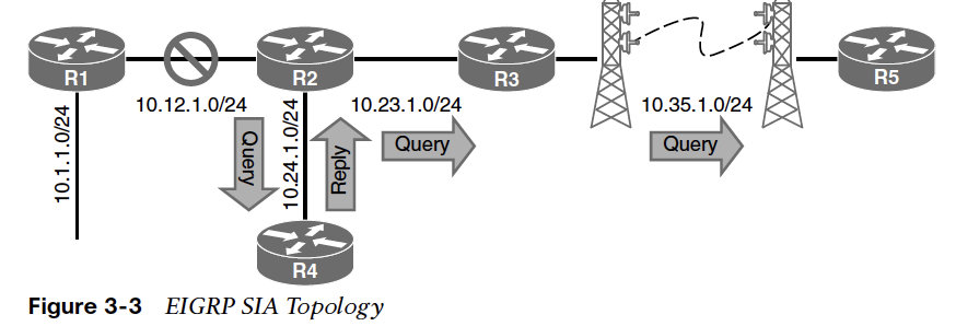
EIGRP SIA Topology
You can only troubleshoot active EIGRP prefixes when the router is waiting for a reply. You show active queries with the command show ip eigrp topology.
To demonstrate the SIA process, Figure 3-3 illustrates a scenario in which the link between R1 and R2 failed. R2 sends out queries to R4 and R3. R4 sends a reply back to R2, and R3sends a query on to R5.
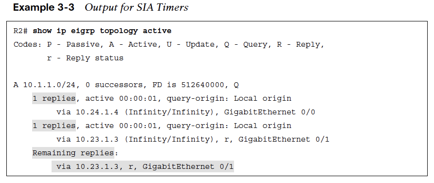
Output for SIA Timers
Using the show ip eigrp topology active command on R2 gets the output shown in Example 3-3.
-
The router next to the peer’s IP address (10.23.1.3) indicates that R2 is still waiting on the reply from R3 and that R4 responded. The command is then executed on R3, and R3 indicates that it is waiting on a response from R5.
-
When you execute the command on R5, you do not see any active prefixes, which implies that R5 never received a query from R3. R3’s query could have been dropped on the radio tower connection.
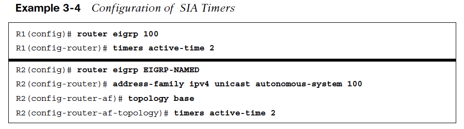
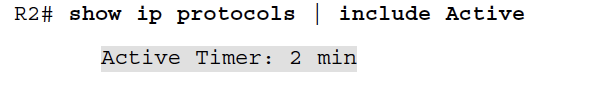
Configuration of SIA Timers
The active timer is set to 3 minutes by default.
-
The active timer can be disabled or modified with the command timers active-time {disabled | 1-65535-minutes} under the EIGRP process.
-
With classic configuration mode, the command runs directly under the EIGRP process, and with named mode configuration, the command runs under the topology base.
Example 3-4 demonstrates the modification of SIA to 2 minutes for R1 in classic mode and R2 in named mode. You can see the active timer by examining the IP protocols on a router with the command show ip protocols. R2’s SIA timer is set to 2 minutes
Route Summarization
-
Scalability of an EIGRP autonomous system depends on route summarization. As the size of an EIGRP autonomous system increases convergence may take longer.
-
Scaling an EIGRP topology depends on summarizing routes in a hierarchical fashion.
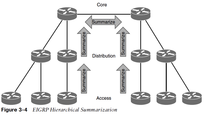
EIGRP Hierarchical Summarization
Figure 3-4 shows summarization occurring at the access, distribution, and core layers of the network topology.
In addition to shrinking the routing table of all the routers, route summarization creates a query boundary and shrinks the query domain when a route goes active during convergence, thereby reducing SIA scenarios.
Interface-Specific Summarization
EIGRP summarizes network prefixes on an interface-by-interface basis.
-
A summary aggregate is configured for the EIGRP interface.
-
The summary aggregate prefix is not advertised until a prefix matches it.
-
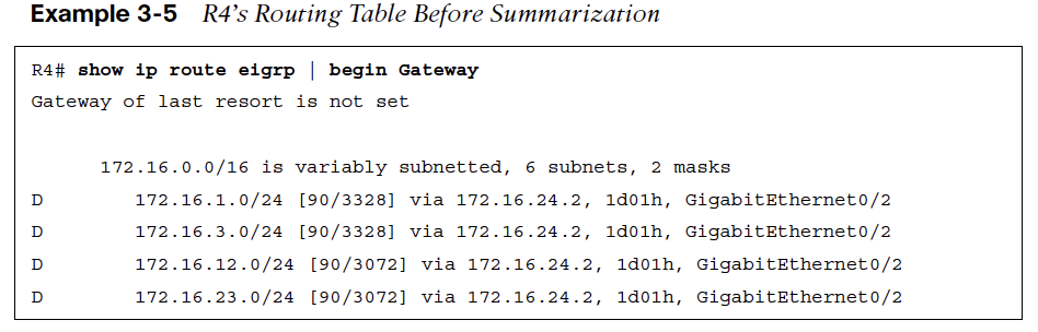
Interface-specific summarization can be performed in any portion of the network topology. Figure 3-5 illustrates the concept of EIGRP summarization.
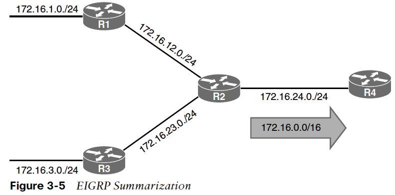
EIGRP Summarization
The advertisement of summary routes occurs on an interface-by-interface basis. Example 3-5 shows R4’s routing table before summarization is configured on R2.
-
For classic EIGRP configuration mode, you use the interface parameter command ip summary address eigrp as-number network subnet-mask [leak-map route-map-name] to place an EIGRP summary aggregate on an interface.
-
For named mode under the af-interface interface-id, use the command summary-address network subnet-mask [leak-map route-map-name].
The leak-map option allows the advertisement of the routes identified in the route map.
Configuration for EIGRP Summarization
Example 3-6 shows the configuration for the 172.16.0.0/16 summary route that is advertised toward R4 out the Gi0/4 interface.
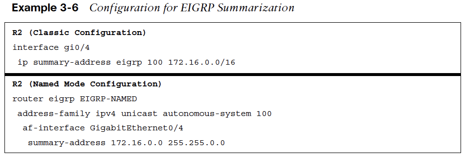
Summary routes are always advertised based on the outgoing interface. The af-interface default option cannot be used with the summary-address command. It requires the use of a specific interface.
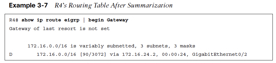
Example 3-7 shows R4’s routing table after summarization is enabled on R2.
Summary Discard Routes
EIGRP installs a discard route on the summarizing routers as a routing loop prevention mechanism.
-
A discard route is a route that matches the summary aggregate prefix with the destination Null0. This prevents routing loops where portions of the summarized network range do not have a more specific entry in the Routing Information Base (RIB) on the summarizing router.
-
The AD for the Null0 route is 5 by default. You view the discard route by using the show ip route network subnet-mask command, as shown in Example 3-8.
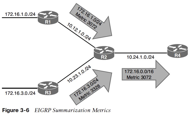
EIGRP Summarization Metrics
-
The summarizing router uses the lowest metric of the component routes in the summary aggregate prefix. The path metric for the summary aggregate is based on the path attributes of the path with the lowest metric.
-
In Figure 3-6, R2 has a path metric of 3072 for 172.16.1.0/24 prefix and a path metric of 3328 for the 172.16.3.0/24 prefix.
-
Every time a matching component route for the summary aggregate is added or removed, EIGRP must verify that the summary route is still using the attributes from the path with the lowest metric.
-
The fluctuation in the path metric is resolved by statically setting the metric on the summary aggregate with the command summary-metricnetwork {/prefix-length | subnet-mask} bandwidth delay reliability load MTU
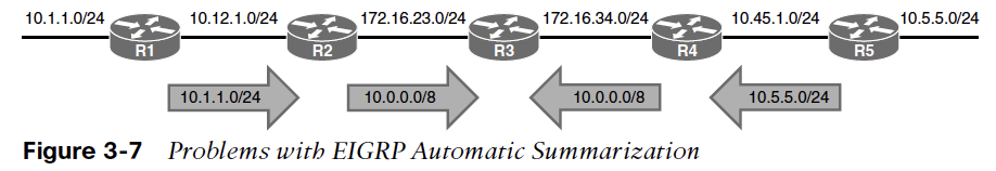
Automatic Summarization
EIGRP supports automatic summarization, automatically summarizing network advertisements when they cross a classful network boundary.
Figure 3-7 shows automatic summarization for the 10.1.1.0/24 route on R2 and the 10.5.5.0/24 network on R4. R2 and R4 only advertise the classful network 10.0.0/8 toward R3.
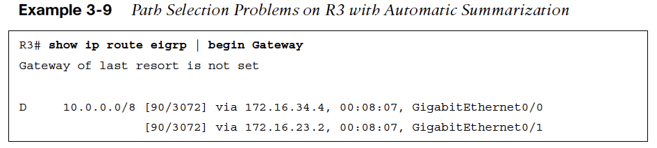
Example 3-9 shows the routing table for R3. Notice that there are no routes for the 10.1.1.0/24 or 10.5.5.0/24 networks; there is only a route for 10.0.0.0/8 with next hops of R2 and R4.
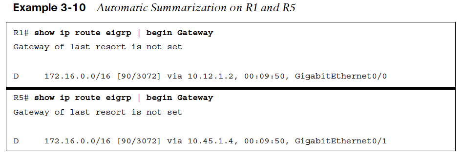
Example 3-10 displays a similar behavior for the 172.16.23.0/24 and 172.16.34.0/24 networks as they are advertised as 172.16.0.0/16 networks from R2 to R1. The identical advertisement occurs from R4 to R5, too.
WAN Considerations
-
EIGRP does not change behavior based on the media type of an interface. Serial and Ethernet interfaces are treated the same.
-
Some WAN topologies may require special consideration for bandwidth utilization, split horizon, or next-hop self.
WAN Connectivity Between Two Data Centers
To overcome single point of failure, you can add additional routers at each site, add redundant circuits (possibly with different service providers), use different routing protocols, or use virtual private network (VPN) tunnels across the internet for backup transport.
Figure 3-8 shows a topology with R1 and R2 providing connectivity at two key data center locations.
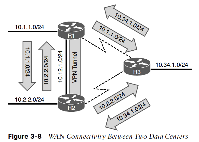
The serial WAN link network advertisements are not illustrated in Figures 3-8 to 3-12, which instead focus on advertisement of routes that are multiple hops away.
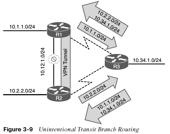
Unintentional Transit Branch Routing
Figure 3-9 demonstrates the failure of the 10 Gbps network link between R1 and R2.
R3 continues to advertise the 10.1.1.0/24 prefix to R2 even though R1’s traffic should be taking the VPN tunnel to reach R2.
The scenario happens in the same fashion with 10.2.2.0/24 traffic transiting R3 instead of going across the VPN tunnel.
The EIGRP stub functionality prevents scenarios like this from happening and allows an EIGRP router to conserve router resources.
EIGRP Stub Router
An EIGRP stub router does not advertise routes that it learns from other EIGRP peers.
-
By default, EIGRP stubs advertise only connected and summary routes, but they can be configured so that they only receive routes or advertise any combination of redistributed routes, connected routes, or summary routes.
-
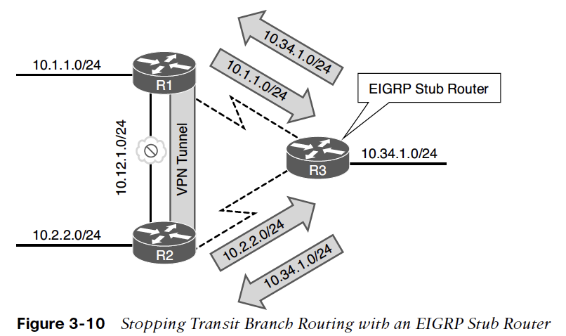
In Figure 3-10, R3 was configured as a stub router, and the 10 Gbps link between R1 and R2 fails. Traffic between R1 and R2 uses the backup VPN tunnel and does not traverse R3’s T1 circuits because R3 is only advertising its connected networks (10.34.1.0/24).
EIGRP Stub Configuration
The EIGRP stub router announces itself as a stub within the EIGRP hello packet.
-
Neighboring routers detect the stub field and update the EIGRP neighbor table to reflect the router’s stub status.
-
If a route goes active, EIGRP does not send EIGRP queries to an EIGRP stub router.
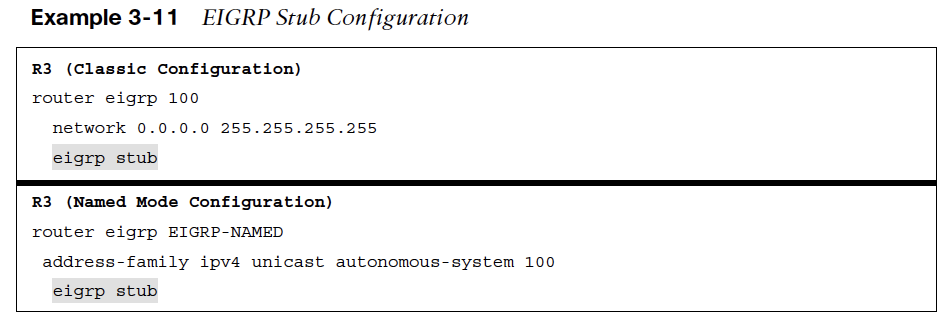
You configure a stub router by placing the command eigrp stub {connected | receive-only | redistributed | static | summary} under the EIGRP process for classic configuration and under the address family for named mode configuration.
Example 3-11 demonstrates the stub configuration for EIGRP classic mode and named mode.
Common Problem with EIGRP Stub Routers
A common problem with EIGRP stub routers is forgetting that they do not advertise EIGRP routes that they learn from another peer.
Figure 3-11 expands on the previous topology and adds the R4 router to the branch network; R4 is attached to R3.
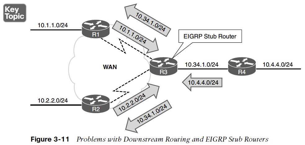
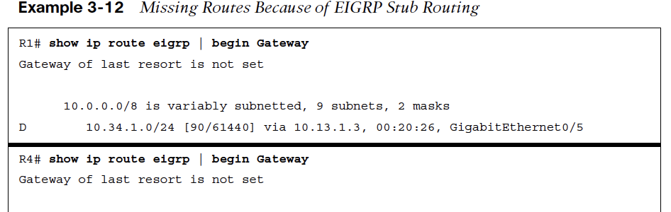
Example 3-12 demonstrates the EIGRP learned routes on R1 and R4.
-
R1 is missing the 10.4.4.0/24 prefix, and R4 is missing the 10.1.1.0/24 prefix.
-
Both prefixes are missing because R3 is an EIGRP stub router.
EIGRP Stub Site Benefits
The EIGRP stub site feature builds on EIGRP stub capabilities that allow a router to advertise itself as a stub to peers only on the specified WAN interfaces but allow it to exchange routes learned on LAN interfaces. EIGRP stub sites provide the following key benefits:
-
EIGRP neighbors on WAN links do not send EIGRP queries to the remote site when a route becomes active.
-
The EIGRP stub site feature allows downstream routers to receive and advertise network prefixes across the WAN.
-
The EIGRP stub site feature prevents the EIGRP stub site route from being a transit site.
EIGRP Stub Site Feature
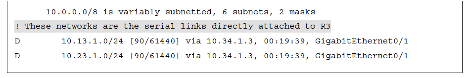
The EIGRP stub site feature works by identifying the WAN interfaces and then setting an EIGRP stub site identifier. Figure 3-12 illustrates R3 being configured as a stub site router and the serial links configured as EIGRP WAN interfaces:
Step 1. R1 advertises the 10.1.1.0/24 route to R3, and the 10.1.1.0/24 route is received on R3’s WAN interface. R3 is then able to advertise that prefix to the downstream router R4.
Step 2. R2 advertises the 10.2.2.0/24 route to R3, and the 10.2.2.0/24 route is received on R3’s other WAN interface. R3 is then able to advertise that prefix to the downstream router R4.
Step 3. R4 advertises the 10.4.4.0/24 network to R3. R3 checks the 10.4.4.0/24 route for the EIGRP stub site attribute before advertising that prefix out either WAN interface. R3 is able to advertise the prefix to R1 and R2 because it does not contain an EIGRP stub site identifier attribute.
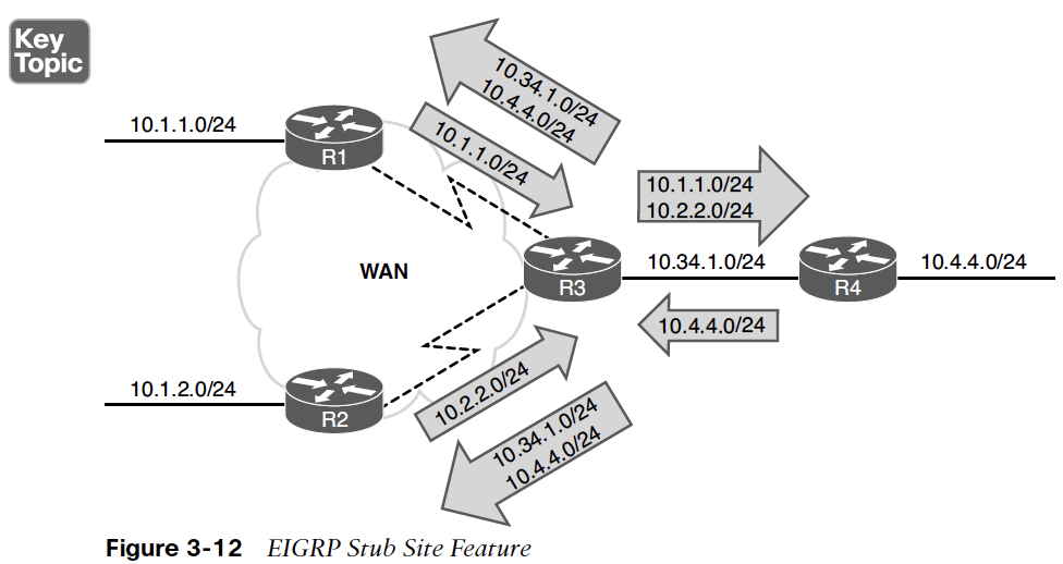
EIGRP Stub Site Config
The EIGRP stub site function is available only in EIGRP named mode configuration.
-
The WAN interfaces are identified underneath the af-interface interface-id hierarchy and use the stub-site wan-interface command.
-
The stub site function and identifier are enabled with the command eigrp stub-site as-number:identifier.
-
The as-number:identifier must remain the same for all devices in a site.
Example 3-13 provides the EIGRP stub site configuration for R3 for both serial interfaces.
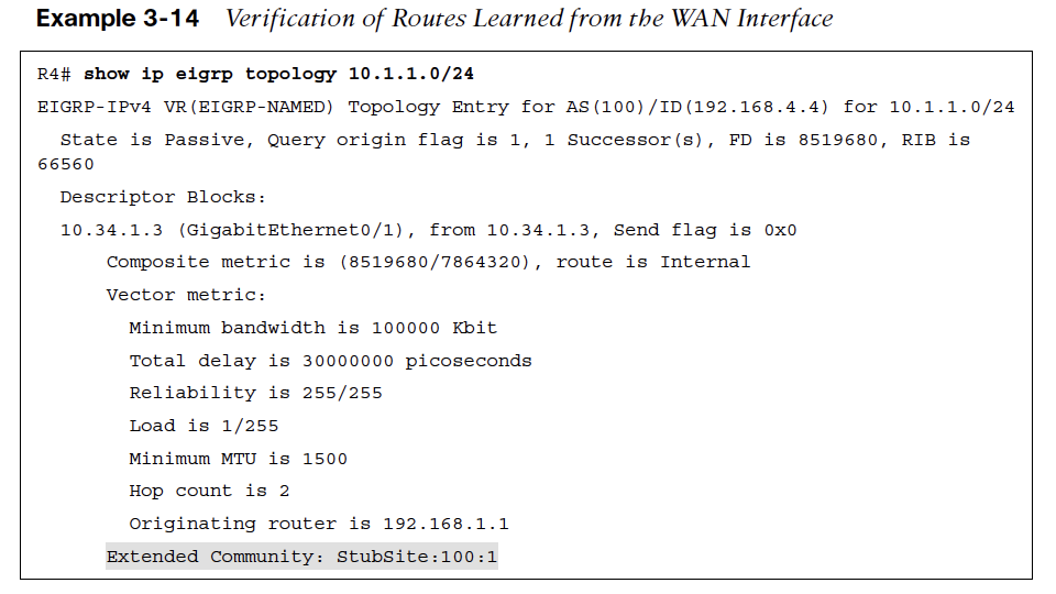
Example 3-14 verifies that the 10.1.1.0/24 route learned from R3’s serial interfaces are tagged with the EIGRP stub site attribute.
EIGRP Stub Router Flags
A major benefit to the EIGRP stub site feature is that the stub functionality can be passed to a branch site that has multiple edge routers.
As long as each router is configured with the EIGRP stub site feature and maintains the same stub site identifier, the site does not become a transit routing site; however, it still allows for all the networks to be easily advertised to other routers in the EIGRP autonomous system.
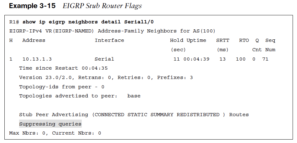
Example 3-15 verifies that R1 recognizes R3 as an EIGRP stub router and does not send it any queries when a route becomes active.
IP Bandwidth Percentage
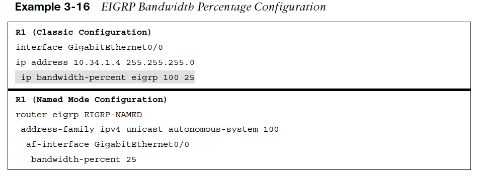
The interface parameter command ip bandwidth percent eigrp as-number percentage changes the EIGRP available bandwidth for a link on EIGRP classic configuration.
The available bandwidth for EIGRP is modified under the af-interface default submode or the af-interface interface-id submode with the command bandwidth-percent percentage in a named mode configuration.
Example 3-16 provides the configuration for setting the bandwidth available for EIGRP on R1.
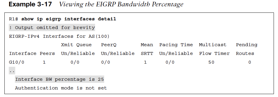
Example 3-17 shows the EIGRP bandwidth settings.
Split Horizon
The first distance vector routing protocols advertised network prefixes out all interfaces for all known routes. Figure 3-13 demonstrates this behavior, with three routers processing the advertisements:
Step 1. R1 advertises the 10.1.1.0/24 network out all of its interfaces.
Step 2. R2 adds to the metric and re-advertises the network to R1 and R3. Advertising a route (10.1.1.0/24) back to the originating router (R1) is known as a reverse route. Reverse routes waste network resources because R1 discards the route from R2 because 10.1.1.0/24 is the connected network and has a higher AD.
Step 3. R3 adds to the metric and advertises the reverse route to R2. R2 discards the route from R3 because it has a higher metric than the route from R1.
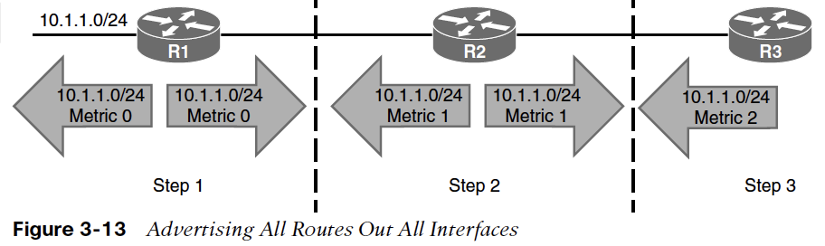
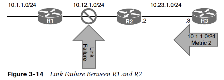
Figure 3-14 demonstrates a link failure between R1 and R2.
-
Split horizon prevents the advertisement of reverse routes and prevents scenarios like the one shown in Figure 3-14 from happening.
-
Figure 3-15 shows the same scenario with split horizon. The following steps occur as R1 advertises the 10.1.10/24 prefix with split horizon enabled:
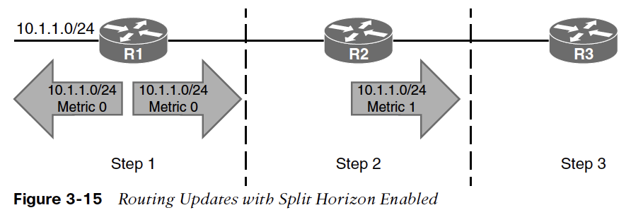
Step 1. R1 advertises the 10.1.1.0/24 network out all of its interfaces.
Step 2. R2 adds to the metric and re-advertises the network to R3 but does not advertise the route back to R1 because of split horizon.
Step 3. R3 receives the route from R2 but does not advertise the route back to R2 because of split horizon.
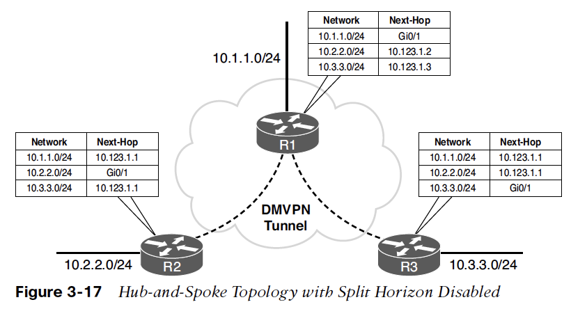
Hub-and-Spoke Topology with Split Horizon
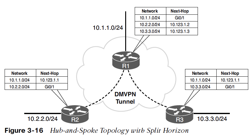
EIGRP enables split horizon on all interfaces by default.
-
Figure 3-16 shows a hub-and-spoke topology where R1 is the hub, and R2 and R3 are spoke routers that can only communicate with the hub router.
-
Notice that the EIGRP routing table is not complete for all the routers.
Disable split horizon on a specific interface by using the interface parameter command no ip split-horizon eigrp as-number with EIGRP classic configuration.
Disable split horizon on EIGRP named mode configuration under the af-interface default or af-interface interface-id, using the command no split-horizon.
Example 3-18 shows a configuration to disable split horizon on the tunnel 100 interface.
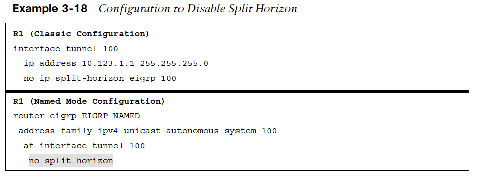
Figure 3-17 shows the routing table of all the routers after split horizon is disabled on R1. Notice that all routers have complete EIGRP routes.
Route Manipulation
-
Route manipulation involves selectively identifying routes that are advertised or received from neighbor routers.
-
The routes can be modified to alter traffic patterns or removed to reduce memory utilization or to improve security.
-
The following sections explain how routes are removed with filtering or modified with an EIGRP offset list.
Route Filtering
EIGRP supports filtering of routes as they are received or advertised from an interface.
Filtering of routes can be matched against:
-
Access control lists (ACLs) (named or numbered)
-
IP prefix lists
-
Route maps
-
Gateway IP addresses
As shown in Figure 3-18, inbound filtering drops routes prior to the DUAL processing, which results in the routes not being installed into the RIB because they are not known.
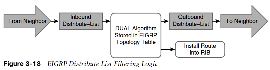
However, if the filtering occurs during outbound route advertisement, the routes are processed by DUAL and are installed into the local RIB of the advertising router.
EIGRP Distribution List Filtering
Filtering is accomplished with the command distribute-list {acl-number | acl-name | prefix prefix-list-name | route-map route-map-name | gatewayprefix-list-name} {in | out} [interface-id].
-
EIGRP classic configuration places the command under the EIGRP process, while named mode configuration places the command under the topology base.
-
Prefixes that match against deny statements are filtered, and prefixes that match against a permit are passed.
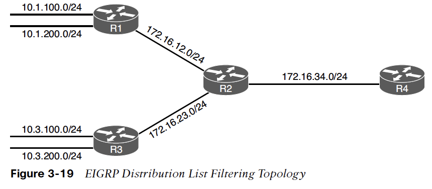
EIGRP Router Filter Config & Verification
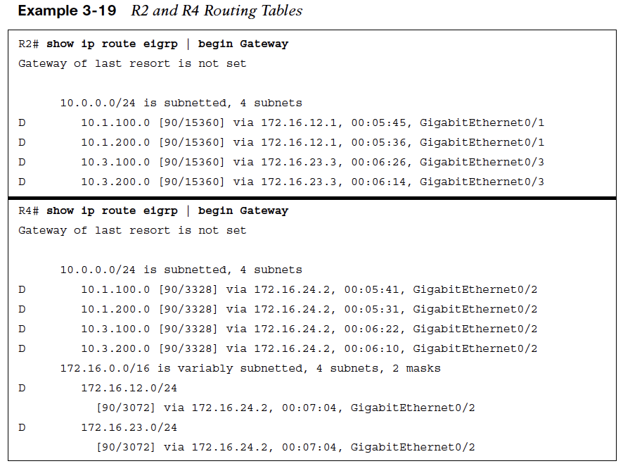
Example 3-19 shows the routing tables of R2 and R4 before the route filtering is applied.
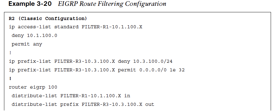
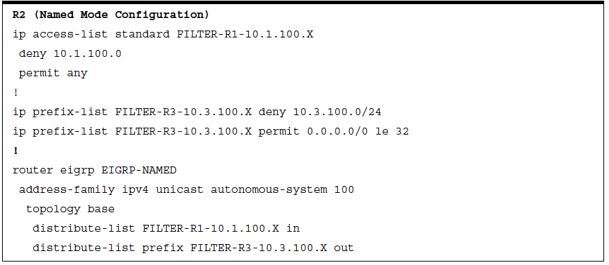
Example 3-20 shows the configuration of R2 to demonstrate inbound filtering of 10.1.100.0/24 and outbound filtering of 10.3.100.0/24.
Example 3-21 shows the routing table on R2 and R4 after EIGRP filtering is enabled on the routers.

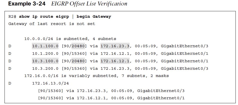
Traffic Steering with EIGRP Offset Lists
Offset lists allow for the modification of route attributes based on the direction of the update, a specific prefix, or a combination of direction and prefix.
-
An offset list is configured with the command offset-list offset-value {acl-number | acl-name] {in | out} [interface-id] to modify the metric value of a route.
-
Specifying an interface restricts the conditional match for the offset list to the interface that the route is received or advertised out of.
-
EIGRP classic configuration places the command under the EIGRP process, while named mode configuration places the command under the topology base.
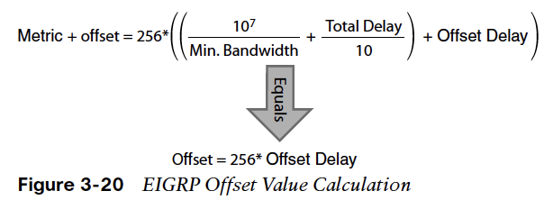
Figure 3-20 shows the modified path metric formula when an offset delay is included.
EIGRP Offset List Topology
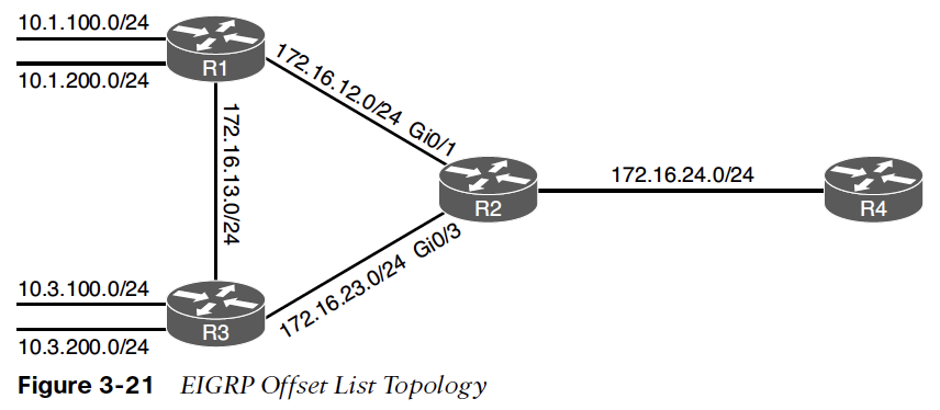
Figure 3-21 shows an EIGRP topology that helps demonstrate EIGRP offset lists.
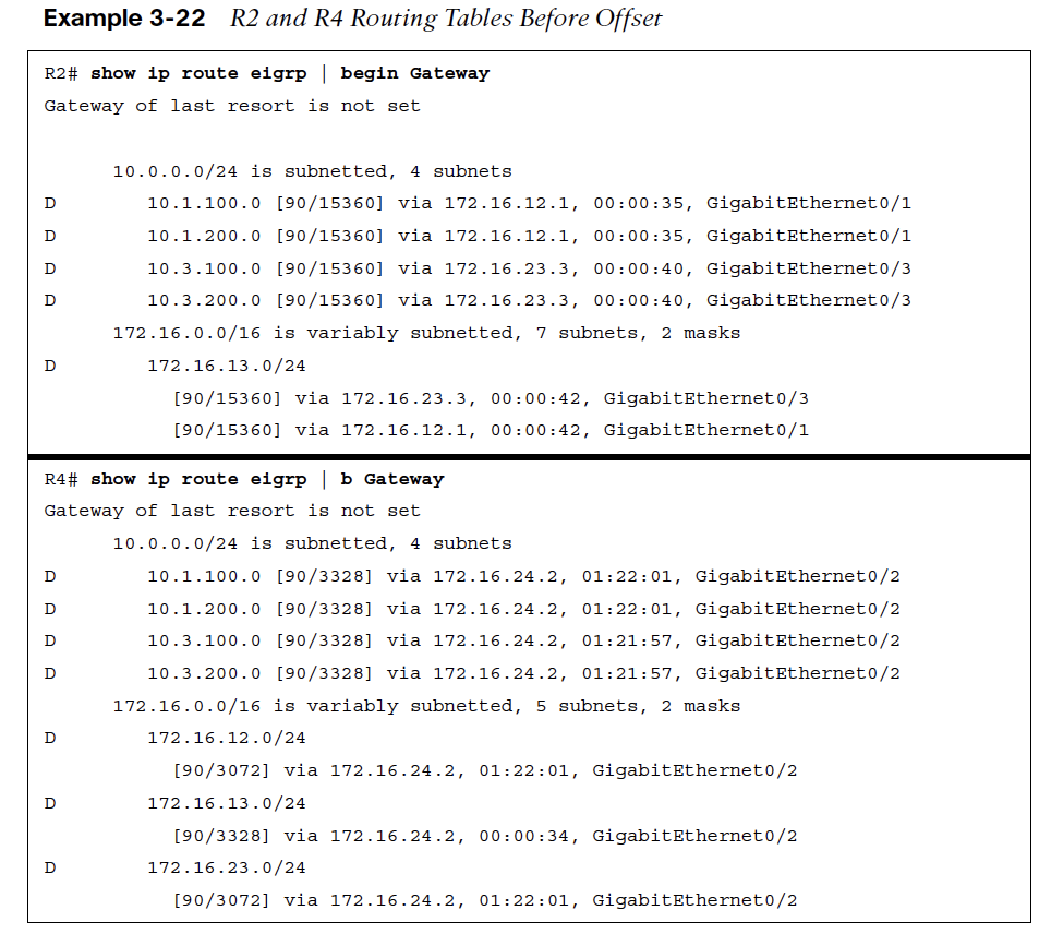
Example 3-22 shows the EIGRP routing tables for R2 and R4 before any path metric manipulation is performed.
EIGRP Offset Configuration
To demonstrate how an offset list is used to steer traffic, the path metric for the 10.1.100.0/24 network is incremented on R2’s Gi0/1 interface so that R2 forwards packets toward R3 for that network. In addition, the 10.3.100.0/24 network is incremented on R2’s Gi0/1 interface so that R2 forwards packets toward R1 for that network.
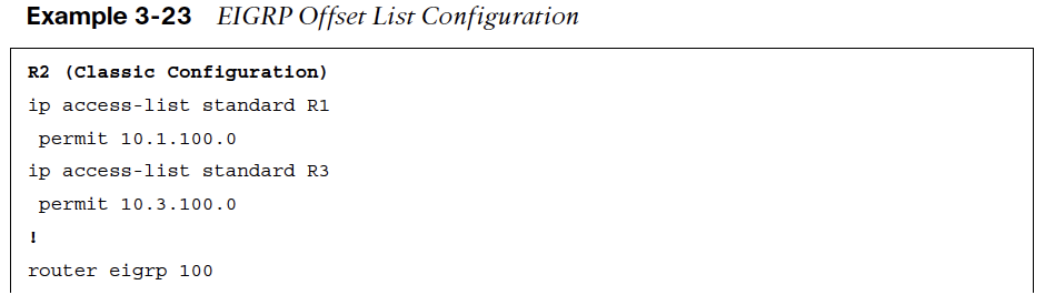
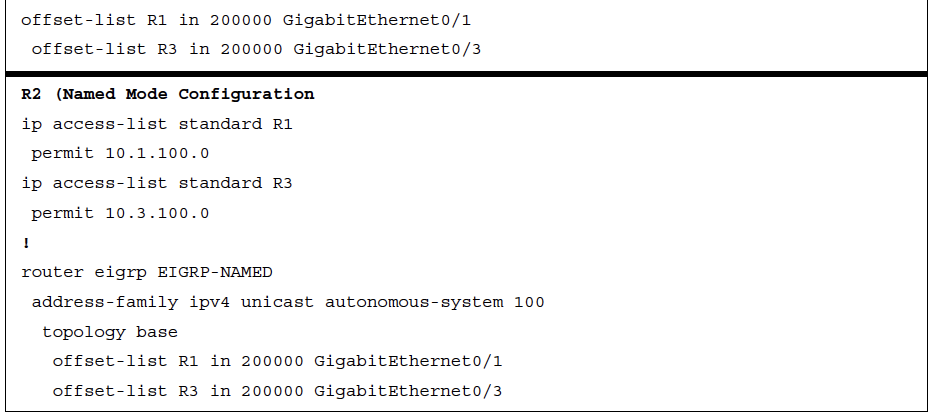
Example 3-23 displays the configuration of R2.
Example 3-24 shows R2’s routing table after the offset list is implemented.