Content
This chapter covers the following content:
-
Spanning Tree Protocol Fundamentals - This section provides an overview of howswitches become aware of other switches and prevent forwarding loops.
-
Rapid Spanning Tree Protocol - This section examines the improvements made to STP for faster convergence.
Spanning Tree Protocol Fundamentals
-
Spanning Tree Protocol (STP) enables switches to become aware of other switches through the advertisement and receipt of bridge protocol data units (BPDUs).
-
STP operates by selecting a master switch and running a tree-based algorithm to identify which redundant ports should not forward traffic.
Spanning Tree Versions
STP has multiple iterations:
-
802.1D, which is the original specification
-
Per-VLAN Spanning Tree (PVST)
-
Per-VLAN Spanning Tree Plus (PVST+)
-
802.1W Rapid Spanning Tree Protocol (RSTP)
-
802.1S Multiple Spanning Tree Protocol (MST)
Note: Catalyst switches now operate in PVST+, RSTP, and MST modes. All three of these modes are backward compatible with 802.1D.
IEEE 802.1D STP Port States
Every port transitions through the following states:
| Port States | Description |
|---|---|
| Disabled | The port is in an administratively off position (that is, shut down). |
| Blocking | The switch port is enabled, but the port is not forwarding any traffic. |
| Listening | The switch port has transitioned from a blocking state and can now send or receive only BPDUs. |
| Learning | The switch port can modify the MAC address table. The switch still does not forward any other network traffic besides BPDUs. |
| Forwarding | The switch port can forward all network traffic and can update the MAC address table as expected. |
| Broken | The switch has detected a problem on a port that can have major effects. The port discards packets as long as the problem continues to exist. |
802.1D STP Port Types
The 802.1D STP standard defines the following three port types:
| Port Types | Description |
|---|---|
| Root port (RP) | A network port that connects to the root bridge or an upstream switch in the spanning-tree topology. There should be only one root port per VLAN on a switch. |
| Designated port (DP) | A network port that receives and forwards BPDU frames to other switches. Designated ports provide connectivity to downstream devices and switches. There should be only one active designated port on a link. |
| Blocking port | A network that is not forwarding traffic because of STP calculations. |
STP Key Terminology
| Terms | Description |
|---|---|
| Root Bridge | The most important switch. All ports are in a forwarding state and are categorized as designated ports. |
| Bridge protocol data unit (BPDU) | Used to identify a hierarchy and notify of changes in the topology. There are two types of BPDUs: configuration BPDU and topology change notification BPDU. |
| Configuration BPDU | Used to identify the root bridge, root, designated, and blocking ports. |
| Topology change notification (TCN) BPDU | Used to communicate changes in the Layer 2 topology to other switches. |
| Root path cost | The combined cost for a specific path toward the root switch. |
| System priority | This 4-bit value indicates the preference for a switch to be root bridge. The default value is 32,768. |
| System ID extension | This 12-bit value indicates the VLAN that the BPDU correlates. |
| Root bridge identifier | This is a combination of the root bridge system MAC address, system ID extension, and system priority of the root bridge. |
| Local bridge identifier | This is a combination of the local switch’s bridge system MAC address, system ID extension, and system priority of the root bridge. |
| Max age | Maximum length of time that passes before a bridge port saves its BPDU information. The default value is 20 seconds. |
| Hello time | The time that a BPDU is advertised out of a port. The default value is 2 seconds, but the value can be configured to 1 to 10 seconds. |
| Forward delay | The amount of time that a port stays in a listening and learning state. The default value is 15 seconds. |
STP Path Cost
-
The root path is found based on the cumulative interface STP cost to reach the root bridge.
-
The interface STP cost was originally stored as a 16-bit value with a reference value of 20 Gbps.
-
Another method, called long mode, uses a 32-bit value and uses a reference speed of 20 Tbps.
-
The original method, known as short mode, is the default mode.
| Link Speed | Short-Mode STP Cost | Long-Mode STP Cost |
|---|---|---|
| 10 Mbps | 100 | 2,000,000 |
| 100 Mbps | 19 | 200,000 |
| 1 Gbps | 4 | 20,000 |
| 10 Gbps | 2 | 2,000 |
| 20 Gbps | 1 | 1,000 |
| 100 Gbps | 1 | 200 |
| 1 Tbps | 1 | 20 |
| 10 Tbps | 1 | 2 |
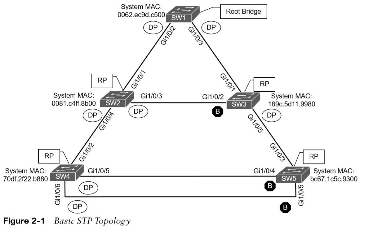
Building the STP Topology
-
This section focuses on the logic switches use to build an STP topology.
-
The focus is on VLAN 1, but VLANs 10, 20, and 99 also exist.
-
SW1 has been identified as the root bridge, and the RP, DP, and blocking ports have been identified.
Root Bridge Election
The first step with STP is to identify the root bridge.
As a switch initializes, it assumes that it is the root bridge and uses the local bridge identifier as the root bridge identifier.
It then listens to its neighbor’s configuration BPDU and does the following:
-
If the neighbor’s configuration BPDU is inferior to its own BPDU, the switch ignores that BPDU.
-
If the neighbor’s configuration BPDU is preferred to its own BPDU, the switch updates its BPDUs to include the new root bridge identifier along with a new root path cost that correlates to the total path cost to reach the new root bridge.
-
This process continues until all switches in a topology have identified the root bridge switch.
-
STP prefers lower priority number then goes to lower MAC address.
STP Root Path Costs
-
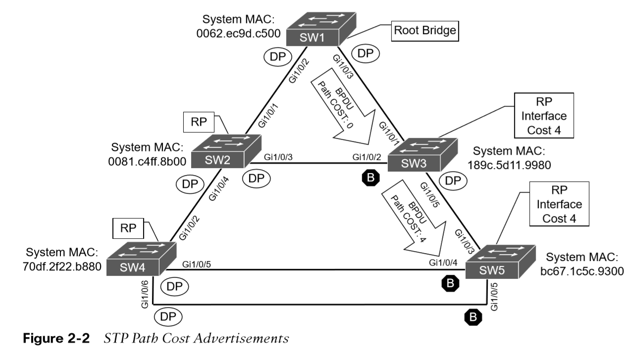
The advertised root path cost is always the value calculated on the local switch.
-
The local root path cost is the advertised root path cost plus the local interface port cost.
-
The root path cost is always zero on the root bridge.
-
Figure 2-2 illustrates the root path cost as SW1 advertises the configuration BPDUs toward SW3 and then SW3’s configuration BPDUs toward SW5.
Locating Root Ports
Once the Root Bridge is found, the switch must determine its Root Port.
The RP is selected using the following logic:
-
The interface associated to lowest path cost is more preferred.
-
The interface associated to the lowest system priority of the advertising switch is preferred next.
-
The interface associated to the lowest system MAC address of the advertising switch is preferred next.
-
When multiple links are associated to the same switch, the lowest port priority from the advertising switch is preferred.
-
When multiple links are associated to the same switch, the lower port number from the advertising switch is preferred.
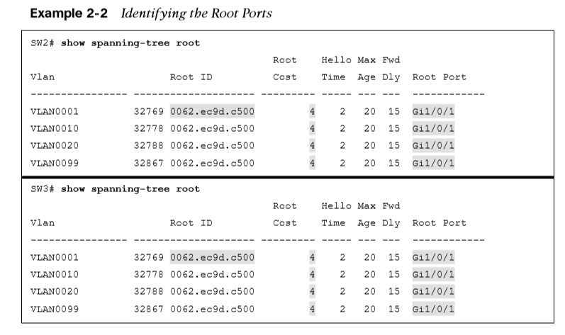
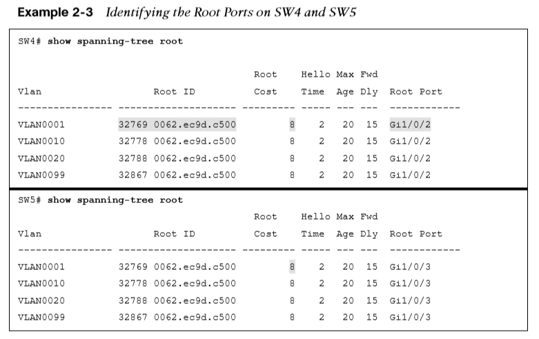
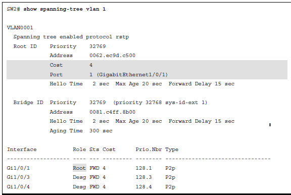
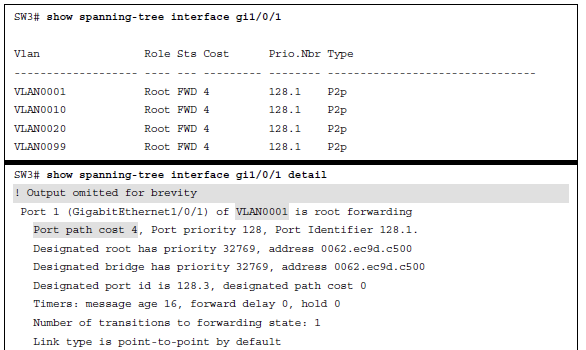
Locating Root Ports Verified
Use the show spanning-tree root command to verify the Root ID and the Root Port.
Locating Blocked Designated Switch Ports
The RPs have been identified and all other ports are considered designated ports. If two non-root switches are connected to each other on their designated ports, one port must be set to a blocking state to prevent a forwarding loop. Calculate which ports should be blocked between two non-root switches:
-
The interface is a designated port and must not be considered an RP.
-
The switch with the lower path cost to the root bridge forwards, and the one with the higher path cost blocks. If they tie, they move on to the next step.
-
The system priority of the local switch is compared to the system priority of the remote switch. The local port is moved to a blocking state if the remote system priority is lower than that of the local switch. If they tie, they move on to the next step.
-
The system MAC address of the local switch is compared to the system priority of the remote switch. The local designated port is moved to a blocking state if the remote system MAC address is lower than that of the local switch. If the links are connected to the same switch, they move on to the next step.
Viewing STP Information
These port types are expected on Catalyst switches:
Point-to-point (P2P) - This port type connects with another network device (PC or RSTP switch).
P2P edge - This port type specifies that portfast is enabled on this port.
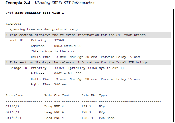
Verify Cost and Root Ports with the show spanning-tree vlan 1 command.

Verify VLAN Information on a Trunk
If a VLAN is missing on a trunk port, check the trunk port configuration for accuracy.
STP Topology Changes
BPDUs always flow from the root bridge toward the edge switches, unless there are changes in the topology.
-
The switch that detects a link status change sends a topology change notification (TCN) BPDU toward the root bridge out of its RP.
-
If an upstream switch receives the TCN, it sends out an acknowledgment and forwards the TCN out its RP to the root bridge.
-
Upon receipt of the TCN, the root bridge creates a new configuration BPDU with the Topology Change flag set, and it is then flooded to all the switches.
-
When switches receive this, they set their MAC address timer to a default 15 seconds. Then the device flushes its MAC table if has not heard from a device in that last 15 seconds.
-
TCNs are generated on a VLAN basis, so the impact of TCNs directly correlates to the number of hosts in a VLAN.
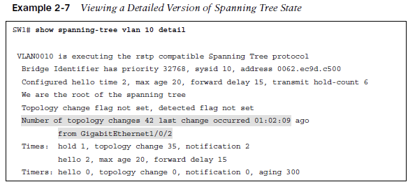
Verify STP Topology Changes
Use the show spanning-tree vlan # detail command to see topology changes.
Converging with Direct Link Failures
When a switch loses power or reboots, or when a cable is removed from a port, the Layer 1 signaling places the port into a down state, which can notify other processes, such as STP.
STP considers such an event a direct link failure and can react in one of three ways:
-
The link between SW2 and SW3 fails. If the link is already blocking there is no impact to traffic between the two switches as they both transmit data through SW1. Both SW2 and SW3 will advertise a TCN toward the root switch, which results in the Layer 2 topology flushing its MAC address table.
-
The link between SW1 and SW3 fails. Network traffic from SW1 or SW2 toward SW3 is impacted because SW3 Gi1/0/2 port is in a blocking state.
-
The link between SW1 and SW2 fails. Network traffic from SW1 or SW3 toward SW2 is impacted because SW3’s Gi1/0/2 port is in a blocking state.
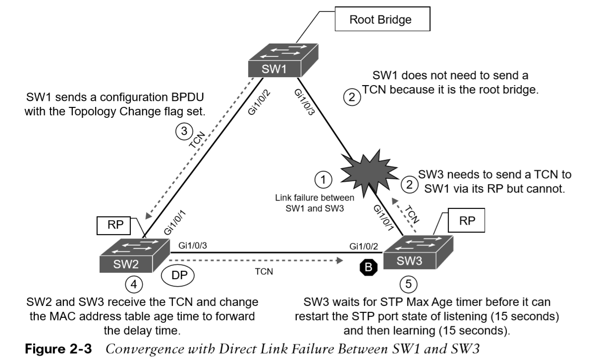
The link between SW1 and SW3 fails.
Phase 1. SW1 detects a link failure on its Gi1/0/3 interface. SW3 detects a link failure on its Gi1/0/1 interface.
Phase 2. Normally SW1 would generate a TCN flag out its root port, but it is the root bridge, so it does not. SW1 would advertise a TCN if it were not the root bridge.
SW3 removes its best BPDU received from SW1 on its Gi1/0/1 interface because it is now in a down state. At this point, SW3 would attempt to send a TCN toward the root switch to notify it of a topology change; however, its root port is down.
Phase 3. SW1 advertises a configuration BPDU with the Topology Change flag out of all its ports. This BPDU is received and relayed to all switches in the environment.
Phase 4. SW2 and SW3 receive the configuration BPDU with the Topology Change flag. These switches then reduce the MAC address age timer to the forward delay timer to flush out older MAC entries. In this phase, SW2 does not know what changed in the topology.
Phase 5. SW3 must wait until it hears from the root bridge again or the Max Age timer expires before it can reset the port state and start to listen for BPDUs on the Gi1/0/2 interface (which was in the blocking state previously).
The link between SW1 and SW2 fails.
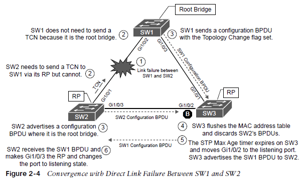
Phase 1. SW1 detects a link failure on its Gi1/0/1 interface. SW2 detects a link failure on its Gi1/0/3 interface.
Phase 2. Normally SW1 would generate a TCN flag out its root port, but it is the root bridge, so it does not. SW1 would advertise a TCN if it were not the root bridge.
SW2 removes its best BPDU received from SW1 on its Gi1/0/1 interface because it is now in a down state. At this point, SW2 would attempt to send a TCN toward the root switch to notify it of a topology change; however, its root port is down.
Phase 3. SW1 advertises a configuration BPDU with the Topology Change flag out of all its ports. This BPDU is then received and relayed to SW3. SW3 cannot relay this to SW2 as its Gi1/0/2 port is still in a blocking state. SW2 assumes that it is now the root bridge and advertises configuration BPDUs with itself as the root bridge.
Phase 4. SW3 receives the configuration BPDU with the Topology Change flag from SW1. SW3 reduces the MAC address age timer to the forward delay timer to flush out older MAC entries. SW3 receives inferior BPDUs from SW2 and discards them as it is still receiving superior BPDUs from SW1.
Phase 5. The Max Age timer on SW3 expires, and now the Gi1/0/2 port on SW3 transitions from blocking to listening state. SW3 can now forward the next configuration BPDU it receives from SW1 to SW2.
Phase 6. SW2 receives the configuration BPDU of SW via SW3 and recognizes it as superior. It marks its Gi1/0/3 interface as the root port and transitions it to the listening state.
Total convergence time for SW2 is 52 seconds.
Indirect Failures
STP communication between switches is impaired or filtered while the network link remains up. This situation is known as an indirect link failure, and timers are required to detect and remediate the topology.
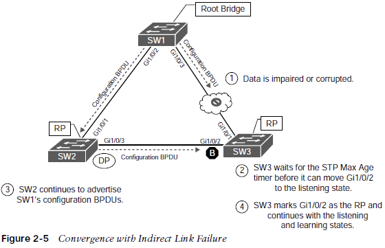
There is an impediment or data corruption on the link between SW1 and SW3.
Phase 1. An event occurs that impairs or corrupts data on the link. SW1 and SW3 still report a link up condition.
Phase 2. SW3 stops receiving configuration BPDUs on its RP. It keeps a cached entry for the RP on Gi1/0/1. Configuration BPDUs from SW1 that are being transmitted via SW2 are discarded as its Gi1/0/2 port is in a blocking state.
Once the Max Age timer expires on SW3 and flushes the cached entry of the RP, SW3 transitions Gi1/0/2 from blocking to listening state.
Phase 3. SW2 continues to advertise the configuration BPDUs from SW1 toward SW3.
Phase 4. SW3 receives SW1’s configuration BPDU via SW2 on its Gi1/0/2 interface. This port is now marked as the RP and continues to transition through the listening and learning states.
The total time for re-convergence on SW3 is 52 seconds.
Rapid Spanning Tree Protocol
-
IEEE 802.1D has only one topology tree and a slower convergence which can be problematic.
-
Rapid Spanning Tree Protocol (RSTP) IEEE 802.1W reduces the number of port states to be faster and more efficient.
Rapid Spanning Tree Port States
IEEE 802.1D has only one topology tree which can be problematic. Larger environments with multiple VLANs need different STP topologies for traffic engineering purposes.
-
Cisco created the proprietary Per-VLAN Spanning Tree (PVST) and Per-VLAN Spanning Tree Plus (PVST+)
-
Rapid Spanning Tree Protocol (RSTP) IEEE 802.1W reduces the number of port states to three:
| Port States | Description |
|---|---|
| Discarding | The switch port is enabled, but the port is not forwarding any traffic to ensure that a loop is not created. |
| Learning | The switch port modifies the MAC address table. The switch still does not forward any other network traffic besides BPDUs. |
| Forwarding | The switch port forwards all network traffic and updates the MAC address table as expected. |
Rapid Spanning Tree Port Roles
RSTP defines the following port roles:
| Port Roles | Description |
|---|---|
| Root port (RP): | A network port that connects to the root bridge or an upstream switch in the spanning-tree topology. There should be only one root port per VLAN. |
| Designated port (DP): | A network port that receives and forwards BPDU frames to other switches. Designated ports provide connectivity to downstream devices and switches. There should be only one active designated port on a link. |
| Alternate port: | A network port that provides alternate connectivity toward the root switch through a different switch. |
| Backup port: | A network port that provides link redundancy toward the current root switch. A backup port exists only when multiple links connect between the same switches. |
Rapid Spanning Tree Port Types
RSTP defines three types of ports that are used for building the STP topology:
| Port Roles | Description |
|---|---|
| Edge Port | A port at the edge of the network where hosts connect to the Layer 2 topology with one interface and cannot form a loop. These ports directly correlate to ports that have the STP portfast feature enabled. |
| Root port | A port that has the best path cost toward the root bridge. There can be only one root port on a switch. |
| Point-to-Point port | Any port that connects to another RSTP switch with full duplex. Full-duplex links do not permit more than two devices on a network segment, so determining whether a link is full duplex is the fastest way to check the feasibility of being connected to a switch. |
| Multi-access connections (Hubs) must use 802.1D. |
Building the RSTP Topology
RSTP switches exchange handshakes with other RSTP switches to transition through the following STP states faster. They establish a bidirectional handshake across the shared link to identify the root bridge.
The process proceeds as follows:
1. As the first two switches connect to each other, they verify that they are connected with a point-to-point link by checking the full-duplex status.
2. They establish a handshake with each other to advertise a proposal (in configuration BPDUs) that their interface should be the DP for that port.
3. There can be only one DP per segment, so each switch identifies whether it is the superior or inferior switch, using the same logic as in 802.1D for the system identifier (that is, the lowest priority and then the lowest MAC address).
4. The inferior switch (SW2) recognizes that it is inferior and marks its local port (Gi1/0/1) as the RP. At that same time, it moves all non-edge ports to a discarding state. At this point in time, the switch has stopped all local switching for non-edge ports.
5. The inferior switch (SW2) sends an agreement (configuration BPDU) to the root bridge (SW1), which signifies to the root bridge that synchronization is occurring on that switch.
6. The inferior switch (SW2) moves its RP (Gi1/0/1) to a forwarding state. The superior switch moves its DP (Gi1/0/2) to a forwarding state, too.
7. The inferior switch (SW2) repeats the process for any downstream switches connected to it.